Lotsofhififun I'm going to take your advice and start again on the board and double check everything as I go,thanks.
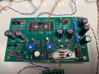
Finally sat down to build this preamp, from complete set.
One channel only lights up, no voltage at T7.
Trying to measure many places, but cant seem to see where it stops. Q1 and 2 near T7 has no power what so ever, power at other Q1 and 2.
Any pointers appreciated!
(And how is the best way to attach images here?🙂)
One channel only lights up, no voltage at T7.
Trying to measure many places, but cant seem to see where it stops. Q1 and 2 near T7 has no power what so ever, power at other Q1 and 2.
Any pointers appreciated!
(And how is the best way to attach images here?🙂)
Attachments
Last edited:
Post with the “Go Advanced” button, that will bring you to page that has “Manage Attachments”
Any pointers appreciated!
Check continuity test on all Nutube pins,
probably some soldering joints need to be reflow gently from both sides 🙂
Reflowed everything from top and bottom, still nothing.
What continuity am i looking for on the pins?
What continuity am i looking for on the pins?
Continuity fine at those points.
Suspecting the jfets near t7.
There is no voltage at any of the feet.
Suspecting the jfets near t7.
There is no voltage at any of the feet.
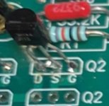
No short, just excess solder. Did a little cleanup. It was like the other Q2 before i started solder from top.
No, i meant there is no short. Just looks like it from my shoddy top solder.
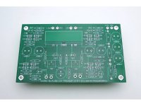
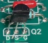
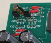
There is no power on any of the jfet feet here, or any side of the resistors, or the 10 uf cap.
There is power on the + side of the 1000 uf caps.
Where does it stop😱
There is no power on any of the jfet feet here, or any side of the resistors, or the 10 uf cap.
There is power on the + side of the 1000 uf caps.
Where does it stop😱
Attachments
Can be around 1000uF caoacitor some cold joints..check all connection both sides ?
Make continuity tests of all components soldering joints together with pcb tracks if doubts..
🙂 Anyways always useful tests
Make continuity tests of all components soldering joints together with pcb tracks if doubts..
🙂 Anyways always useful tests
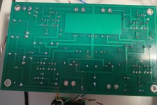
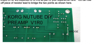
If i do a continuity test from q1 D to q2 G, i get some beeps at the working channel, other channel is silent.
EDIT: HAHAHA. found it.
I have the V1R0 board 😉
EDIT: HAHAHA. found it.
I have the V1R0 board 😉
Attachments
Last edited:
 Something to learn every day
Has anyone integrated a mute circuit between the B1 and the output RCAs? I'm pretty sure I'm going to do something like this: https://www.diyaudio.com/forums/analog-line-level/323336-mute-circuit.html#post5450128
I'd be controlling the relay with an Arduino, so that's not a problem but I don't quite know what he means by "Choose a value of resistor to suit the amplifier in use". My only guess would be using a resistor that matches the input impedance of my power amp. But his example of 1k seems way low. Any suggestions?
Thanks all, this is an amazing preamp and community.
What about simple switch ?
For example 2 positions for two different RCA inputs and nr 3 position for mute.
For example 2 positions for two different RCA inputs and nr 3 position for mute.
Has anyone integrated a mute circuit between the B1 and the output RCAs? I'm pretty sure I'm going to do something like this: https://www.diyaudio.com/forums/analog-line-level/323336-mute-circuit.html#post5450128
I'd be controlling the relay with an Arduino, so that's not a problem but I don't quite know what he means by "Choose a value of resistor to suit the amplifier in use". My only guess would be using a resistor that matches the input impedance of my power amp. But his example of 1k seems way low. Any suggestions?
Thanks all, this is an amazing preamp and community.
pot wipers to GND
no need for resistors in mute route, just switch from wiper to GND , manual or relay
- Home
- Amplifiers
- Pass Labs
- B1 with Korg Triode