Just thinking out loud, it's possible that leading H2 (positive) would tend to mask the leading edge (transient) of the fundamental. It may be similar to why higher slew rate and lower TIM tend to sound better, at least to some folks.
Also, trailing H2 (negative) may be more like reverberation or room reflections, even though the time constant is so short, it should be inaudible.
Question:
Is it feasible to use complementary Jfets and a bipolar supply in the buffers before and after the Nutube? Something like B1 Rev2 which is also the buffer in front of the transformer in the M2.
This would mean a few things:
A) No caps (OK, might need cap on output...it will depend on stability)
B) The buffer stages would be push pull (could be good or bad)
C) You would need a bipolar power supply
D) Pricey 2SK170/2sj74 pairs
I have built both the regular B1 (SE) and the B1 Rev2 (Push Pull). I preferred regular b1. Rev2 was a little too "insightful" if you know what I mean. But if you add the NuTube in there for harmonics it might be a nice combo.
Attachments
Hi
I am not ZM, so sorry for the thread jack, but as ZM helped me out on this...
You can use 0.22uF for the first cap in the signal path, 1uF for the second and whatever is needed for the 3rd, as that depends on the input impedance of your power amp/next stage.
In my case, I went for 3.3uF for the last one to enable « in case of » an easy sub 10k entry impedance power amp to follow, which is really worst reasonable case, but as space wasn’t a concern anymore because that one wouldn’t fit on the board anyway, why bother !
BUT the value of that 3rd cap is in a linear relationship, so if your power amp has say a 100k input impedance (ten times my worst case), then you simply divide by ten my value => 0.3uF
And so forth, depending on the relation between your input impedance and the 10k in the above example.
You may even go for smaller values, but at the cost of the bass frequency response, say if you don't have full range speakers etc. but then you better ask first, the above is full proof and always Ok in the audio band.
For more info on caps you can read post 2601 andthe following.
I hope it helps -and saves ZM some time... mic back to ZM!
Claude
The formula for the -3dB Low Frequency rolloff is: f = 1/(2piR*C)
R will be the input impedance of the following stage. Or the power amplifier following the preamplifier. You should at least design for 10 kOhms. A few inverting amplifiers have very low input impedance like the original Electrocompanier. I do not remember the number though.
R will be the input impedance of the following stage. Or the power amplifier following the preamplifier. You should at least design for 10 kOhms. A few inverting amplifiers have very low input impedance like the original Electrocompanier. I do not remember the number though.
Yes, may I add that for full range speakers you want to chose 5Hz as cut off frequency, so not to have to much loss at 20Hz...
Claude
Claude
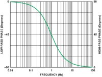
I believe a speaker company, B&W probably, DSPed a high pass phase response. The subjective (listening) test showed a preference for the corrected phase response. (I think the -3 dB points were identical.) An argument for a low cutoff => larger capacitors.
Attachments
Question:
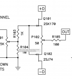
Is it feasible to use complementary Jfets and a bipolar supply in the buffers before and after the Nutube?
Something like B1 Rev2 which is also the buffer in front of the transformer in the M2.
This would mean a few things:
A) No caps (OK, might need cap on output...it will depend on stability)
B) The buffer stages would be push pull (could be good or bad)
C) You would need a bipolar power supply
D) Pricey 2SK170/2sj74 pairs
I have built both the regular B1 (SE) and the B1 Rev2 (Push Pull). I preferred regular b1. Rev2 was a little too "insightful" if you know what I mean.
But if you add the NuTube in there for harmonics it might be a nice combo.
I am not qualify expert but cap's block DC if 2SJ74/2SK170 have none but AC only
( tighty matched jfet's or adjusted by trimmer offset ) at his output, then logically no need 10uF capacitor at the buffer output.
DIY entusiast Professor Akihiko Kaneta use a lot bipolar supply's and avoid caps if possible
despite more complicated design and complex builds.
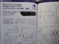
Korg triode is very popular in Japan two examples : MC phono and Headphone amp
MJ1904_(05)Nutube-hyhbrid-MC-preamp_KanedaA.pdf - Google Drive
MJ1905_(06)Nutube-hyhbrid-MC-preamp_KanedaA.pdf - Google Drive
MJ1611_(04)Nutube-6P1-headphone-amp_NagashimaK.pdf - Google Drive
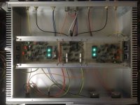
Pictures show Korg Nutube with Silicon Carbide Mosfets power amplifier
video : DC amp No.262 NuTube Hybrid Batterydrive Power IVC2
Attachments
Last edited:
I am not qualify expert but cap's block DC if 2SJ74/2SK170 have none but AC only (tighty matched jfet's or adjusted by trimmer offset) at his output, then logically no need 10uF capacitor at the buffer output.
DC from the buffer can be eliminated using this configuration, however you still have DC from the Nutube plate to deal with. So a blocking cap is still needed.
Same for the input. The DC for the grid bias needs to be blocked.
And if the source has any DC, then this needs to be blocked as well using a third cap to avoid a noisy volume pot.
Therefore, this design needs a minimum of two caps if your source is AC coupled. Or three to play it on the safe side.
Just thinking out loud, it's possible that leading H2 (positive) would tend to mask the leading edge (transient) of the fundamental.
I don't know what the underlying psycho acoustic phenomenon might be,
assuming even that there is one.
I did speculate, idly. that it might be tied into our neural networks need to
interpret whether something is approaching or receding, a skill that
would have survival value.
I fired up my B1 for the first time and want to confirm the voltages. I'm using a regulated linear supply (AMB s11), and the output from that is 23.97V. The output on the s11 is determined by a Zener diode and a ratio of 2 resistors, so the tolerance of those 3 components will determine the end-result voltage.
With this, everything is pretty much up to spec except T3 which I have 22.44V.
Now, this does seem very marginal, but the guide says that values should fall within 0.5V, and in this case I'm slightly out of spec. I think the build is fine as all other test points are exact.
Would you leave this as-is, or perhaps try a slightly lower value resistor on the CRC to drop less voltage?
Complementary jfet's buffer logically bring radical changes in bias circuit as well plate etc.Therefore, this design needs a minimum of two caps if your source is AC coupled. Or three to play it on the safe side.
My post was about others Korg audio circuit with bipolar psu and is show less capacitors use is possible
B1 with Korg Triode
Attachments
Hi . I have the Pass preamp with a Korg triode and much appreciate it. I like listening to loud music, but my wife doesn't, so to keep everyone happy I want to buy a set of Bluetooth headphones.
If I buy a small Bluetooth transmitter box make a signal for the headphones, where do I connect it in the preamp? The signal path in the preamp goes as follows : from the input rca sockets to the input selector, from here to the volume attenuator and from here to the tube buffer, from where it goes to the output rca sockets.
Do I take my signal for the Bluetooth transmitter from between the input selector and the attenuator, or between the attenuator and the buffer ,or after the buffer?
Does anyone know of a high quality diy Bluetooth transmitter, that could be built into the preamp chassis. Cheers
- Home
- Amplifiers
- Pass Labs
- B1 with Korg Triode