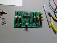
Thank's ! I did only set the bias at 9,5 Volts and I am very satisfied with the result in the musical rendering ! For more details, go to : https://www.diyaudio.com/forums/the-diyaudio-store/343087-korg-b1-completion-kit-pioneer-batch-feedback-4.html#post5934211
Last edited:
Noob question... Is it bad practice on input wires to the Pot, to twist a single ground and both + channel input wires together in a run? Or do I need to run separate twisted -/+ pairs to each input RCA?
I think that that's better to run separate twisted +/- pairs to each input RCA to avoid intermodulation between the two channels R and L !
But I just realized that I did the opposite ! So it's not too important...
Last edited:
That's what I figured since most do it that way in the builds I've seen. Thanks for the reply!
What’s the purpose of twisting the cables. They look neater that way and might conceivably reduce some back EMF over longer distances. I just replaced hookup wire in ACA with solid core that would have been a nightmare to twist up. The more questions I ask the smarter I get!
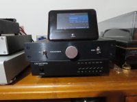
Just finished up my pre amp now, its 03:06 in the morning here in Norway..

More images and impressions will come during the weekend.
But so far, i am so pleased with it.
More images and impressions will come during the weekend.
But so far, i am so pleased with it.
PCB built and put in chassis, still to do internal wiring though
Attachments
Last edited:
It’s in the B1K article writtent by Nelson Pass. You can find a link to it in the DIY Audio store B1K kit listing.
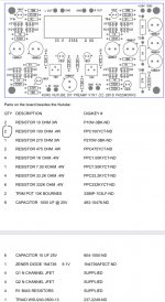
There are some incorrect BOMs out there. Check the components on your board layout vs the BOM you reference. I've asked Nelson to correct them. But so far I see nothing corrected.
There are some incorrect BOMs out there. Check the components on your board layout vs the BOM you reference. I've asked Nelson to correct them. But so far I see nothing corrected.
The schematic in the B1 article on firstwatt.com is updated and correct. The silkscreen matches this schematic.
http://www.firstwatt.com/pdf/art_diy_nutube_preamp.pdf
The schematic printed out and included in the (first batch only) kit of parts is one of the older versions. My error. Use the schematic in the article and/or just stuff the parts into the PCB as labeled, the silk is correct.
Experts don't need BOMs...
So you would recommend an expert in, let’s say, avionics manufacturing should abandon their BOMs? Mark that was a bone headed comment.
View attachment 784455
The white capacitors at output are also away now. Use the 10 uf electrolytics. But the the 3 Vdc was there even after the white capacitors where gone.
Finally, a build that is messier than mine. Yay!
So many works of art in here it makes me feel guilty.
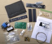
Just starting my build. Supporting the store and all that have contributed to this project. I built the Pete Millett head amp awhile back and know how the vibrations affect the Korg tube.
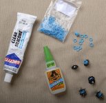
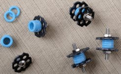
Rather than buy a commercial isolator, with the spirit of DIY here is my take on some homemade isolators. Please note the attempt at Pass blue. These are silicon dampers used in keyboards. A few cents apiece. The grids they are mounted on is some plastic screen I had on hand. Some 3mm screws and a stack of four dampers with the circuit board in place along with the tallest component will fit. Hopefully this will help some on vibrations. The two adhesives I found that would work with the dampers I bought are shown in one of the photos.
More to follow.
Attachments
The schematic in the B1 article on firstwatt.com is updated and correct. The silkscreen matches this schematic.
http://www.firstwatt.com/pdf/art_diy_nutube_preamp.pdf
The schematic printed out and included in the (first batch only) kit of parts is one of the older versions. My error. Use the schematic in the article and/or just stuff the parts into the PCB as labeled, the silk is correct.
I believe that the BOM in the article states that only two 100 ohm resistors are needed when 4 are needed. This has been brought up a few times in the thread as mentioned by Bullitt a few posts back. Following the BOM along with the Silkscreen on the board as 6L6 mentioned will help.
Attachments
Last edited:
Finally, a build that is messier than mine. Yay!
So many works of art in here it makes me feel guilty.
Yes I only care about sound. And problems before it is finnished make it messy. My problem was hum because I used bus instead off starground.
Last edited:
Does anyone have an internal wiring diagram for the B1k?
It might take me a while to figure this out on my own.
It might take me a while to figure this out on my own.
I just read up about ground connections. I think connection the ground of L and R together at the input would be good. Then only one gnd connection to the potentiometer, common for the two channels.Please excuse the sketch, but it's all I have at the moment -
The grounds on the output are bussed in the drawing, I have done it that way as well as individually, both ways work equally well.
And now that I'm looking at the sketch, It's not correct, the grounds at the input are wrong. I'm removing the drawing now and will re-draw it later.
And now that I'm looking at the sketch, It's not correct, the grounds at the input are wrong. I'm removing the drawing now and will re-draw it later.
- Home
- Amplifiers
- Pass Labs
- B1 with Korg Triode