Pass DIY Addict
Joined 2000
Paid Member
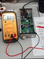
For some reason I have 9V across the input connectors. All other readings are fine. Where have I gone wrong?
Nothing is wrong, this is a function of the caps that are in place and having no load/connection to your RCA jacks. I was a little alarmed to find this on mine when I first built it, but it's fine.
Eric
Were you measuring between L/R Input to Gnd?
I'll have to measure mine when I get home to see if it does the same. Interesting!
I'll have to measure mine when I get home to see if it does the same. Interesting!
@avtech yes L/R to ground.
@eric thank you that has put my mind to rest; thought I'd gone wrong somewhere.
@eric thank you that has put my mind to rest; thought I'd gone wrong somewhere.
Pass DIY Addict
Joined 2000
Paid Member
Glad to hear it, Marra! I did the same thing - my first iteration included a straight line to RCA jacks. I nearly fell over when I connected my DMM across the terminals on the board! With the pot in place, everything is better behaved!
Glad to hear it, Marra! I did the same thing - my first iteration included a straight line to RCA jacks. I nearly fell over when I connected my DMM across the terminals on the board! With the pot in place, everything is better behaved!
Likewise Eric. I had the same thing when I built my Salas Simplistic phono stage which was sorted by soldering a 1M resistor across the output; hadn't thought to equate the same to the front end caps on the B1 Nutube. All is now good and am listening to Oli Brown through the stunt speakers. Happy days😀
installing a power on led
Sorry to be thick but what does this mean in detail for resistor values and connection points?
No reason why not. Just adjust the values of the input resistors to function as a
divider to take the gain down to something around unity.
Sorry to be thick but what does this mean in detail for resistor values and connection points?
Looks good Pat, very neat work.
Stick with it - I fried a couple of components on the way but it worked out in the end. Having a decent, controllable soldering station really helped - a worthwhile investment for me anyway.
Let us know what happens when you power it up.
H
Thanks!
I didn't realize I could test without having source connected and whatnot. I think I can test board as is. But I don't want to temporarily solder the power supply wires in. Do they make something to temporarily plug into pcb holes? As I don't think alligator clips would work well.
Last edited:
One approach is to use PCB screw terminal blocks, 5mm pitch, (green plastic thingies). I have soldered these to the board whilst testing and evaluating, but will desolder them and solder the wiring directly to the board when everything is finalised.Thanks!
I didn't realize I could test without having source connected and whatnot. I think I can test board as is. But I don't want to temporarily solder the power supply wires in. Do they make something to temporarily plug into pcb holes? As I don't think alligator clips would work well.
Last edited:
I've been working on a simple LTSpice simulation for the B1 Korg Pre and have had a couple of requests to share.
So here we go 😉
It is unfinished, unpolished and I am still at the 'fumbling along' stage, but seems to be operating reasonably accurately.
Varying the values of the R5 and R7 changes the plate voltage (as per the board 10k pots) - remember to keep total to 10k.
I set the input signal to get a 1V output for the purpose of being able to compare the distortion and harmonic figures given in Nelson's document with the Spice Error Log and FFT outputs.
R17 was required to get the correct bias voltage at the cathode. Without it the voltage sits around 9v instead of 0.6v.
Nutube LTSpice model was from the ever helpful Jazbo8 on this thread here Vacuum Tube SPICE Models.
Component designations are arbitrary as I haven't had a chance to tidy them up yet. This is very much a work in progress but hopefully a good start for anyone wishing to play around with the circuit.
(I can't upload the .sub file so I have attached it as a .txt. Rename the extension ".sub", place in the same folder as the .asc and it should work).
Attachments
One approach is to use PCB screw terminal blocks, 5mm pitch, (green plastic thingies). I have soldered these to the board whilst testing and evaluating, but will desolder them and solder the wiring directly to the board when everything is finalised.
Do you have some suggested parts numbers? Can these also be used for signal input and output?
Personally, I have no problem with using screw contacts for power and signal. Cleaning contacts and wires with Caig DeOxit, followed by Caig DeOxit Shield, and for signals, Mapleshade SilClear, before use seems to work for me.
Thank-you for parts reference
Thank you very much, 6L6!
Thank you very much, 6L6!
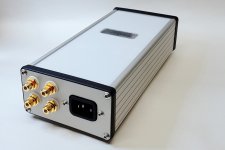
I'd just like to say thanks to Nelson for the circuit (sounds superb) and to all the other contributors that have put their time into guiding us mere mortals. 
Thanks also to Algar_emi whose PCB layout I built.
Pretty happy with how this one turned out and how it sounds.
Thanks also to Algar_emi whose PCB layout I built.
Pretty happy with how this one turned out and how it sounds.
Attachments
to avtech23 #2235
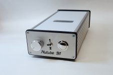
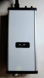
I like your soundmachine! NUTUBE visible at toplid - also nice.
I hope you like the sound of your little giant like I enjoy my NUTUBE!
Lay back, listen and enjoy....
Greets
Dirk
I like your soundmachine! NUTUBE visible at toplid - also nice.
I hope you like the sound of your little giant like I enjoy my NUTUBE!
Lay back, listen and enjoy....
Greets
Dirk
I'd just like to say thanks to Nelson for the circuit (sounds superb)....
Curious question: what's the 1/2 switch on the front used for? I only see 4 RCAs on the back.
- Home
- Amplifiers
- Pass Labs
- B1 with Korg Triode