Hello!
I recently inherited a bunch of stuff from a fellow DIYer, and one of the things was a nice chassis suitable for a preamp or perhaps Chipamp with an outboard PSU. Discussions with other members, as well as a healthy dose of curiosity led me to choose the B1. It went together very easily and quickly. Here is the log of that build.
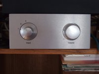
The finished product. It sounds fantastic!
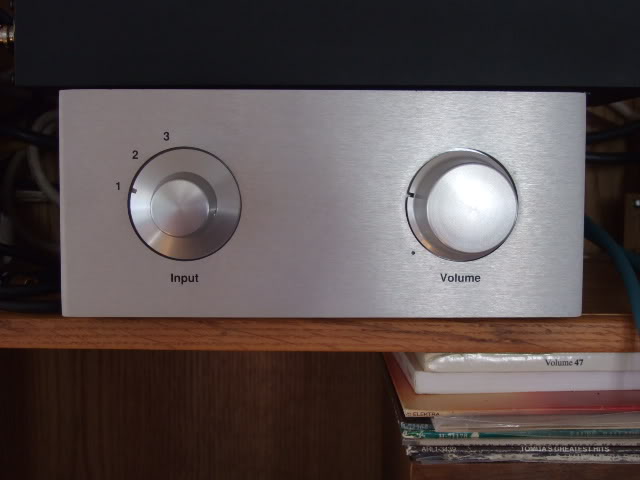
But how did I get there? well...
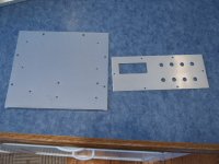
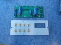
When doing a project like this, the easiest place to begin (for me, anyway...) is the mechanical. Drilling, hardware, things that touch the chassis. Not a lot of drilling was involved, the power inlet module was pre-cut, so I added the holes for the RCA jacks and the screws for the circuit boards and transformer.

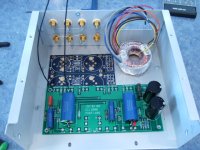
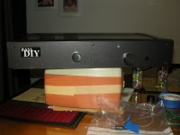
This is just placing the various boards and transformer in place to see how things will fit. The blue board shown in this photo is actually a dual-rail PSU PSB from Peter Daniel, the single rail is exactly half of it.

This is a really nice Goldpoint switch and series stepped attenuator made from a Elna 24 pole switch and a bunch of Holco resistors. It's all wired up because it was salvaged from a different project.
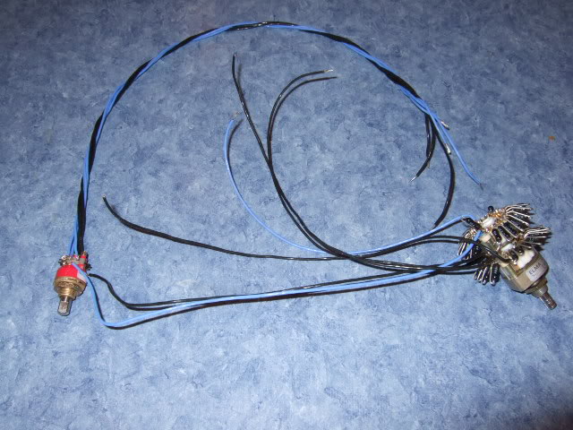
You will notice in this photo that the grounds of the inputs are wired together. This is for two reasons... firstly, the RCA jacks all float on the chassis - the shoulder washers isolate the jack from the chassis. Also, the PassDIY circuit board has a pad for ground on both left and right... so there will be wire connected to one of these negative tabs to the PCB pad.

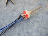
A well-stocked junk box to the rescue!! This switch is the one I had to use in the end... the Goldpoint that was on the harness with the attenuator had a shaft that was just too short to use with the knobs on the chassis. This switch was bought only a few weeks ago as I was perusing through the local surplus store and saw this switch perfect for a preamp. Luck favors the prepared!

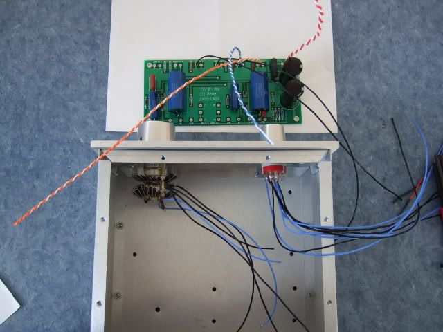
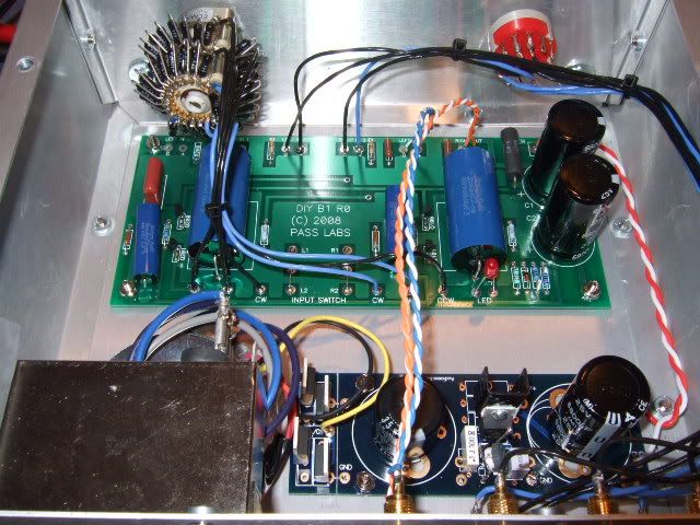
So here are the selector and the attenuator mounted, and the PCB with some of the wires soldered in place. In order to keep the wires as short as comfortable, it is prudent to solder all of one edge in place, and then you only have to do the other edge in place. if you do this, make sure that your wires are at least a couple of inches longer than you know you will need. Too long you can trim, but too short is a pain in the backside!
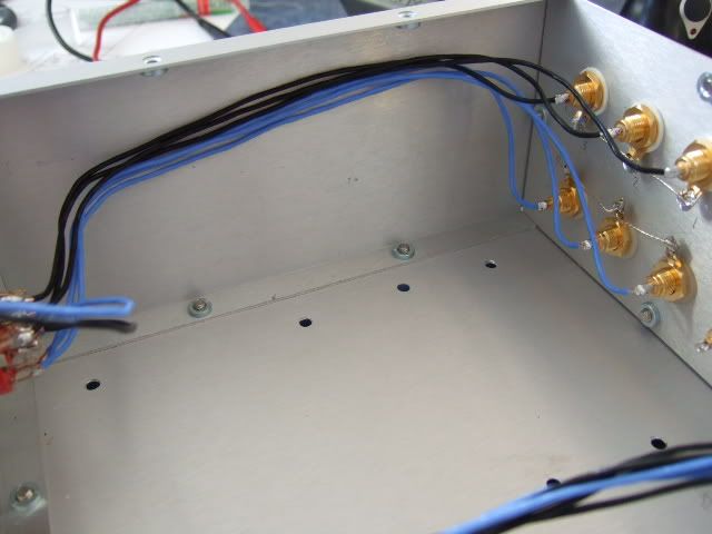
The wiring continues.
I originally envisioned the preamp board turned the other way, to keep the leads from the RCA jacks shorter. The size of the attenuator happened to get in the way of the black electrolytic caps, so it got turned 180deg.
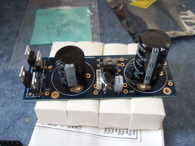
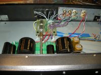
Here is the single-rail universal power supply PCB from Peter Daniel. It's a very nice board, with the ability to choose 2- or 3- pin diodes (or none at all), many different lead spacings on the filter capacitors, and either a LT1085 or LM317 regulator. Shown here are MUR860 diodes and a LM317 regulator.
When I first fired this up I couldn't adjust it to get more than about 7.5-8 volts on the outputs... I was slightly confused, and knowing that just thinking about it wouldn't fix anything, decided to measure the components... It turned out that I grabbed a 240K ohm resistor when I need a 240R... 😀 Anyway, I didn't have anything close to 240, but I happened to have two 150R that are now placed in series in that position, and it works very well now! The range of adjustment is about 17-25 volts, and have it set at 19.5v
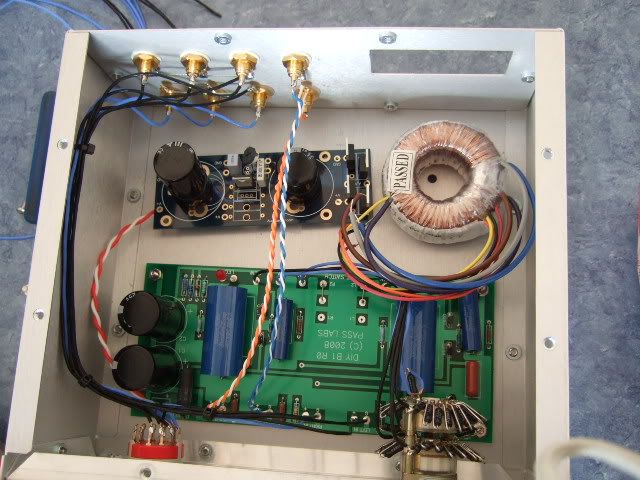
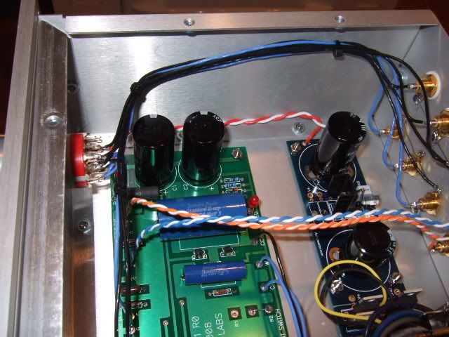
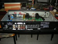
This is the last check of the wiring to see where the power supply wires will place.
Just to recap, the black and blue are signal input, switching and attenuation, the red/white is from psu board to preamp board, and the blue/blue-white, orange/orange-white is the output.
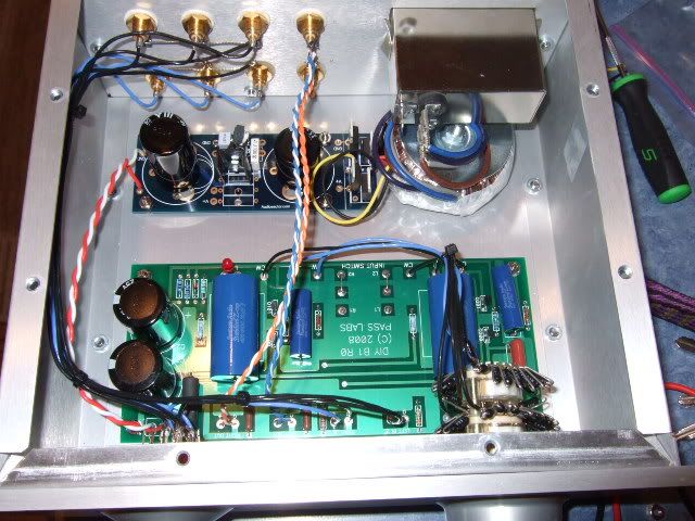
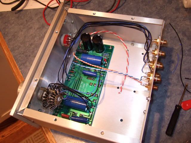
And here it is complete - the power inlet module is installed and above the transformer, the yellow/black leads are the secondary of the transformer.
This was a very easy and rewarding project. I cannot express enough gratitude to both Nelson Pass (you rock!) and Peter Daniels (you also rock!) for making the circuit and and the PSU board. Although something like this could be very easily made on perfboard (and I thought quite seriously about it) any project is greatly simplified by good circuit boards!
I recently inherited a bunch of stuff from a fellow DIYer, and one of the things was a nice chassis suitable for a preamp or perhaps Chipamp with an outboard PSU. Discussions with other members, as well as a healthy dose of curiosity led me to choose the B1. It went together very easily and quickly. Here is the log of that build.
The finished product. It sounds fantastic!
But how did I get there? well...
When doing a project like this, the easiest place to begin (for me, anyway...) is the mechanical. Drilling, hardware, things that touch the chassis. Not a lot of drilling was involved, the power inlet module was pre-cut, so I added the holes for the RCA jacks and the screws for the circuit boards and transformer.
This is just placing the various boards and transformer in place to see how things will fit. The blue board shown in this photo is actually a dual-rail PSU PSB from Peter Daniel, the single rail is exactly half of it.
This is a really nice Goldpoint switch and series stepped attenuator made from a Elna 24 pole switch and a bunch of Holco resistors. It's all wired up because it was salvaged from a different project.
You will notice in this photo that the grounds of the inputs are wired together. This is for two reasons... firstly, the RCA jacks all float on the chassis - the shoulder washers isolate the jack from the chassis. Also, the PassDIY circuit board has a pad for ground on both left and right... so there will be wire connected to one of these negative tabs to the PCB pad.
A well-stocked junk box to the rescue!! This switch is the one I had to use in the end... the Goldpoint that was on the harness with the attenuator had a shaft that was just too short to use with the knobs on the chassis. This switch was bought only a few weeks ago as I was perusing through the local surplus store and saw this switch perfect for a preamp. Luck favors the prepared!
So here are the selector and the attenuator mounted, and the PCB with some of the wires soldered in place. In order to keep the wires as short as comfortable, it is prudent to solder all of one edge in place, and then you only have to do the other edge in place. if you do this, make sure that your wires are at least a couple of inches longer than you know you will need. Too long you can trim, but too short is a pain in the backside!
The wiring continues.
I originally envisioned the preamp board turned the other way, to keep the leads from the RCA jacks shorter. The size of the attenuator happened to get in the way of the black electrolytic caps, so it got turned 180deg.
Here is the single-rail universal power supply PCB from Peter Daniel. It's a very nice board, with the ability to choose 2- or 3- pin diodes (or none at all), many different lead spacings on the filter capacitors, and either a LT1085 or LM317 regulator. Shown here are MUR860 diodes and a LM317 regulator.
When I first fired this up I couldn't adjust it to get more than about 7.5-8 volts on the outputs... I was slightly confused, and knowing that just thinking about it wouldn't fix anything, decided to measure the components... It turned out that I grabbed a 240K ohm resistor when I need a 240R... 😀 Anyway, I didn't have anything close to 240, but I happened to have two 150R that are now placed in series in that position, and it works very well now! The range of adjustment is about 17-25 volts, and have it set at 19.5v
This is the last check of the wiring to see where the power supply wires will place.
Just to recap, the black and blue are signal input, switching and attenuation, the red/white is from psu board to preamp board, and the blue/blue-white, orange/orange-white is the output.
And here it is complete - the power inlet module is installed and above the transformer, the yellow/black leads are the secondary of the transformer.
This was a very easy and rewarding project. I cannot express enough gratitude to both Nelson Pass (you rock!) and Peter Daniels (you also rock!) for making the circuit and and the PSU board. Although something like this could be very easily made on perfboard (and I thought quite seriously about it) any project is greatly simplified by good circuit boards!
Attachments

Last edited:

Nice build. I'm running mine of off an Energizer xp8000 battery right now but may be interest in the specific parts you used for your power supply. Enjoy, its a great little preamp.
Pete
Pete
Nice build. I'm running mine of off an Energizer xp8000 battery right now but may be interest in the specific parts you used for your power supply. Enjoy, its a great little preamp.
Pete
Yes it would. How about a BOM for the Daniel power supply board?
much appreciated!
Russellc
Specific info on the PSU -
Transformer - Avel-Lindberg Y236001 15va 9v+9v Secondaries in series.
Transformers and Power Converters From Avel Lindberg, Inc.
You could also use a Y236004 and parallel the secondaries.
Circuit board - Universal Power supply PCB from Peter Daniel http://www.Audiosector.com This product is not on his website, but email him and he takes care of it quickly. Lots more info on this board here - http://www.diyaudio.com/forums/audio-sector/149672-universal-power-supply-pcb.html
I used the LM317 regulator circuit right from the datasheet - http://cache.national.com/ds/LM/LM117.pdf
This fits directly on the PCB
In my build I populated the board from my local surplus store, so I will have to make a guess as to actual parts from Digi-key...
The first electrolytic cap is a 35v (because the output from the rectifier is close to 30v) 3300uf. Digi-Key - P7607-ND (Manufacturer - ECO-S1VP332BA)
The electrolytic downstream of the regulator is 25v 6800uf . This value was chosen only because it was the biggest thing they had at the store. But it's quiet and sounds great, so here is an equivalent - Digi-Key - P6458-ND (Manufacturer - ECE-S1EG682M)
The TO-220 package diodes are MUR860 diodes - Digi-Key - MUR860GOS-ND (Manufacturer - MUR860G)
Now on to the regulator circuit
Regulator device, LM317 - Digi-Key - LM317TFS-ND (Manufacturer - LM317T)
5K trimpot - this looks like it should work. Solder the wiper to one of the legs. - Digi-Key - 3296W-502LF-ND (Manufacturer - 3296W-1-502LF)
240ohm resistor - http://search.digikey.com/scripts/dksearch/dksus.dll?Detail&name=P240BBCT-ND
.1uf cap - Digi-Key - P4525-ND (Manufacturer - ECQ-V1H104JL)
1.0uf cap - Digi-Key - P4675-ND (Manufacturer - ECQ-V1H105JL)
Hopefully this is of some help to you! Please feel free to contact me via PM or just ask in this thread if you have any questions.
Last edited:
Nice job 6L6, and nice thread too (veni-vidi-vici instead of usual endless/useless blah-blah)! 
Last edited:
Very nice indeed! Thanks for the concise info. I have several of Peters power supply boards on hand, so Im putting one together. The Notebook/laptop power supply I'm now using works fine, but the B-1 deserves something a little more elegant.
Much thanks,
Russellc
Much thanks,
Russellc
Guess its time for me to put in another order for a PD power supply board. Wow another board to populate  . F5, Pearl 2 and now a power supply board for the B1. LOL, I'm in DIY heaven 🙂 .
. F5, Pearl 2 and now a power supply board for the B1. LOL, I'm in DIY heaven 🙂 .Guess its time for me to put in another order for a PD power supply board. Wow another board to populate
Paradise I tell you! I'm in the same boat. I've got so many going, I just keep rotating which one to buy parts for. As one gets close, I focus on it to finish. Shelf time gets longer with each addition. F-5 done. B-1 (was) done. DCB1 hypnotize, partially done, DCB1 mesmerize, partially done, Pearl 2, partially, collected parts
still being collected, Pumpkin, needs rest of build parts, (all matched transistors acquired). I also have boards and transistors for more F-5 builds, but need to order a pile of heatsinks from M&M. Also, boards and parts for a mini Aleph and a large Aleph (4 or 5?). This does not include tube and speaker projects........maybe a government grant of some sort would help!
Russellc

Audio circuit schematic is in this article - http://passdiy.com/pdf/B1 Buffer Preamp.pdf
Audio board for sale here -- DIY Order Form
PSU circuit board - Universal Power supply PCB from Peter Daniel DIY Chip Amplifier Kits, PCB's, Components and Information. This product is not on his website, but email him and he takes care of it quickly. Lots more info on this board here - http://www.diyaudio.com/forums/audio-sector/149672-universal-power-supply-pcb.html
PSU regulator Schematic - http://cache.national.com/ds/LM/LM117.pdf
Gents ,
PSU can be ran at 24vdc .... am I understanding this correctly ?
I had the idea I would used Peter Daniels universal boards and build the same PS for my Pearl .
As being as I'm building a balanced version requiring 2 boards - a symmetrical board with power both ... correct ?
Rich
PSU can be ran at 24vdc .... am I understanding this correctly ?
I had the idea I would used Peter Daniels universal boards and build the same PS for my Pearl .
As being as I'm building a balanced version requiring 2 boards - a symmetrical board with power both ... correct ?
Rich
Just now getting around to soldering this together, a few questions:
1. Where did you put the 240 ohm resistor? is it on the backside? I see it in the regulator manufacturer's schematic, but dont see it on board. Which two points does it attach to? (yeah, I need the specific of instruction😀)
2.With the pot, center leg (wiper) soldered to either leg, then it looks like the other two go in the holes for R2?
Thanks,
Russellc
You are asking about the Peter Daniel Universal PSU, right?
The 240 Ohm resistor is on the front, it's just hiding under the pot in the photo. Install it is the "R1" position, closest to the regulator.
Yes, solder the wiper to one of the legs and install in position "R2"
The 240 Ohm resistor is on the front, it's just hiding under the pot in the photo. Install it is the "R1" position, closest to the regulator.
Yes, solder the wiper to one of the legs and install in position "R2"
The B1 is pretty forgiving with its PSU.
I run mine from a 30VA 9-0-9V into a stock 1A bridge then CRC with 2 x 4700uF LCR caps with 2R2 between them. Reg is a straightforward LM317.
Its actually better than a DCB1 that I am trial building at the moment. I did use Obbligato 10uF Caps though.
The little PCB on the top left is just a Mains Filter that I pinched straight out of a VCR.
The PCB is Home-Brew. Although it is Double Sided there are no tracks on the Upper Surface, just the Ground Plane.
Ever so easy to make at home.
Attachments

Last edited:
The circuit boards are available at Passdiy.com
I don't know if anybody is selling their complete project. Perhaps. 🙂
I don't know if anybody is selling their complete project. Perhaps. 🙂
The circuit boards are available at Passdiy.com
I don't know if anybody is selling their complete project. Perhaps. 🙂
Thanks for ALL your input, much appreciated by a total novice.... All this started because of a thread of mine regarding a 'simple RIAA' circuit modification to my existing little amp....." tubes-valves/213236-tube-pre-amp-both-cd-phono-inputs.html "
The amount of return info has been great.... Any other input or modifications to 'my' circuit will still be gladly received and appreciated... THANKS
Best wishes to all contributors and readers.... Cheers from New Zealand
I just finished a B1 build using the PCB and JFETs from PassDIY and capacitors, Alps Pot and a 6 input rotary switch kit from HiFi Collective.
The case is my old NAD 1300 preamp (1990's vintage) which recently died - hence this project.
I also run the Oatley K303 RIAA amp in a separate box which is fine for my old turntable, a late 60's vintage Dual.
I'm powering the B1 off an old laptop computer PS. It seems to be OK.
I like this preamp. It works really well, sounds great. I need a new CD player now.
Attachments
Thanks for your help!
Here is mine B1:
I guess capacitors still breaking in, so can't tell if I like it better than my Threshold SL-10.
Here is mine B1:
An externally hosted image should be here but it was not working when we last tested it.
I guess capacitors still breaking in, so can't tell if I like it better than my Threshold SL-10.
- Home
- Amplifiers
- Pass Labs
- B1 preamp build thread