B1 PCB
Are there by any chance still B1 preamp PCB's available?
I know they can be made p2p, but the final amp I want to make on an PCB
Nils
Are there by any chance still B1 preamp PCB's available?
I know they can be made p2p, but the final amp I want to make on an PCB
Nils
Are there by any chance still B1 preamp PCB's available?
I know they can be made p2p, but the final amp I want to make on an PCB
Nils
Straight to the man.
DIY Order Form
Hi,
when using a volt. regulator for 24V output, what should the cap value be on the output of the regulator and on the B1 pcb?
with the v.reg, you really don't need 30,000uF or they should still be used?
when using a volt. regulator for 24V output, what should the cap value be on the output of the regulator and on the B1 pcb?
with the v.reg, you really don't need 30,000uF or they should still be used?
Suggested Dale
Gents ,
I'm trying to find the RN-55D .25 watt resistors NP suggested in the PDF .
I found .5 at digikey ,but .25 ..
any suggestions please ?
thank , Rich
Gents ,
I'm trying to find the RN-55D .25 watt resistors NP suggested in the PDF .
I found .5 at digikey ,but .25 ..
any suggestions please ?
thank , Rich
Gents ,
I'm trying to find the RN-55D .25 watt resistors NP suggested in the PDF .
I found .5 at digikey ,but .25 ..
any suggestions please ?
thank , Rich
Try Mouser, Vishay CCF55 series
Vishay Mouser Electronics - Electronic Component Distributor Metal Film Resistors
I had only sent one set of Mezmerize Gerber to Mark. As I see, all boards in Euro store end with an ''e''. Just needs to be moved there the one ending with an ''e'' I guess. Looks like just a logistics code.
...all boards in Euro store end with an ''e''...
After a little more looking I came to the same conclusion, but I was unable to delete my post.
Last edited:
Its a long thread so sorry if this have been covered before.
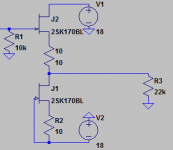
Have anybody here build the buffer stage like this (see attached picture) to get the dc levels of both input and output to be close to 0V?
Of course a presumption is matched and thermally coupled fets but I would still expect some dc-drift but what I would like to know is if its severe enough that I should servo the current source.
Attachments
I had only sent one set of Mezmerize Gerber to Mark. As I see, all boards in Euro store end with an ''e''. Just needs to be moved there the one ending with an ''e'' I guess. Looks like just a logistics code.
Yup, same board, we just put the "e" at the end of the SKU number so we can keep track of which store its going out of. the "Euro" store has different prices as the VAT has been paid.
The Mezmerize are quite popular!
I'm thinking of making one
Good job Salas!
> Have anybody here build the buffer stage like this (see attached picture) to get the dc levels of both input and output to be close to 0V?
Umteen times over many many years, with (like Dennis Feucht) or without source resistor (like Borbely).
http://www.diyaudio.com/forums/pass-labs/124889-b1-buffer-preamp-2.html#post1547019
Best results to be had using matched dual FETs, such as LSK389.
Patrick
Umteen times over many many years, with (like Dennis Feucht) or without source resistor (like Borbely).
http://www.diyaudio.com/forums/pass-labs/124889-b1-buffer-preamp-2.html#post1547019
Best results to be had using matched dual FETs, such as LSK389.
Patrick
Higher value for C100/200
Is it possible to use a capacitor value of 3.3uF instead of 1uF for C100/200? What would the impact be on the sonic qualities of the B1?
Is it possible to use a capacitor value of 3.3uF instead of 1uF for C100/200? What would the impact be on the sonic qualities of the B1?
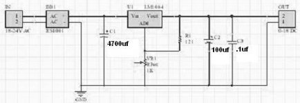
How big cap @ C1,C2 after LM1084 regulated supply?
Hello,
I'm building a stock B-1 Buffer Preamp, with the exception of using a bridge rectified,then series regulated(LM1084) supply feeding the B1 boards. I'm using this regulator because it is on hand and I abhor those switching laptop supplies that abound in the stores (Too much RFI for my taste).
Attached is a pic of the regulator.
The BOM lists the use of 15,000uf caps at C1,C2, but I'm afraid this is overkill (literally, killing the regulator).
I would like to choose smaller, very high quality caps at C1,C2, and would value any recommendations.
Some caps I happen to have on hand are Black Gate 100uf/50v; BG 330uf/50v(in multiples), Nichicon KG 4,700uf/35v and KG 6,800uf/35v.
Completion of the project hinges on these components, so, since I might need to order parts depending on recommendations, I appreciate any prompt responses.
-Chas
Attachments
Connecting Digital volume control to B1
Recently I found the B1 PCB from PASS in my mailbox. 😀😀😀
Previously I asked the possibility to put a digital volume control and input board together with the B1. Dig pot how to connect the output from the pot to the PCB.
For the input I know now, however in the schematic the pot of 25K is the input impedance. The Dig volume board has an input impedance of 47.5K and the output is altered by the CS3310. I did not measure the output impedance of de CS3310 board.
My question related to this output (CS3310) which I want to connect to the input of the B1.
Do I need to implement also a resistor from Wiper to CCW like 100K (suggested by Laurent) to mimic the pot or just place a wire from CW to wire so rout the signal directly to the 1µF Cap?
Any suggestion!
Nils
Killing it in what sense, making it useless?The BOM lists the use of 15,000uf caps at C1,C2, but I'm afraid this is overkill (literally, killing the regulator).
- Home
- Amplifiers
- Pass Labs
- B1 Buffer Preamp