Yes! Buy the PCB from PassDIY and you have the option of buying the genuine, non-counterfit JFETs with the same order.
🙂
🙂
Yes! Buy the PCB from PassDIY and you have the option of buying the genuine, non-counterfit JFETs with the same order.
🙂
Thanks 🙂,
but board costs little more than my budget.I will have to wait for few months.
Regards,
Sachin
Hi Chas,
I have used a voltage regulator using a LM1084 like this one:
LV30 Variable Voltage Regulator 1.5-30V (5A) Kit_Power Supply Kit_Analog Metric Limited - DIY Audio Kit
It works perfectly...
Cheers,
Eric
I used Tangent's TREAD regulated supply and it works famously. No more boards available, though, sadly enough.
Hi
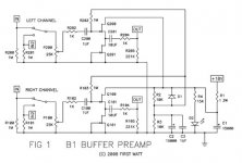
I'm trying to understand the function of the capacitors C100/C200 in the original B1 diagram. Mr. Pass states in his article that 'C100 and C200 are there because the Gate of the JFETs needs to be set at 1⁄2 the DC voltage of the power supply'. But as far as my basic knowledge lets me understand it, according to Kirchoff's laws, there must be some DC current flowing back from the JFETs to P100/P200 and to the inputs, and C100/200 prevent this by blocking this DC current, is that correct? But how exactly do they provide for 1/2 of the DC voltage at the gate of the JFETs? What happens if the value of C100/200 is changed (higher or lower?)
Another question: I see a resistor (R102/202) and a capacitor (C100/200) in series between P100/200 and Q100/200, so I'm thinking this is a nice low pass filter between the signal in and the buffer, with a cut off frequency of about 150Hz. Of course this must be wrong😕 Where did I go wrong?
Attachments
The Peter Daniel universal board is what I used.
Specific information on utilization of that board in a B1 can be found here -- http://www.diyaudio.com/forums/pass-labs/181552-b1-preamp-build-thread.html#post2441197
Specific information on utilization of that board in a B1 can be found here -- http://www.diyaudio.com/forums/pass-labs/181552-b1-preamp-build-thread.html#post2441197
Hi,
C100 blocks DC and passes AC.
Look at the quiescent operation where there is no AC signal to pass.
Imagine that all to the left of C100 is removed, because it has blocked the DC connection.
The gate is insulated from the Drain and from the Source. The Gate is effectively only connected to that 1M (R101) and then on to the junction of R2&R3. Since that Gate in sulated from Darin and Source no current can flow to the Gate through R103. This "no current flow" requires that the voltage at the Gate is exactly the same as the voltage at the junction of R2&R3.
Th,
look at what R2&R3 are connected to. The top is connected to V+ (+18Vdc), the bottom is connected to Audio and Power Ground (0Vdc).
the two resistors are the same value so the resistive ladder they form ensures that the junction sits at half Vsupply. We have (very) effectively biased the input jFET Gate to half the supply voltage.
Precise !
What happened to my typing and my checking/correction procedure.
Can anyone not understand the explanation due to the typing errors?
I can ask the Mods to insert new text if really needed.
What happened to my typing and my checking/correction procedure.
Can anyone not understand the explanation due to the typing errors?
I can ask the Mods to insert new text if really needed.
I see a resistor (R102/202) and a capacitor (C100/200) in series between P100/200 and Q100/200, so I'm thinking this is a nice low pass filter between the signal in and the buffer
Isn't the capacitor, C100, supposed to act as a High Pass filter, or is it C101 that has this honor (i.e. to adjust the high pass corner frequency, is it C100 or C101 whose value we select)?
Sorry if this post is redundant...
-Chas
Polypropylene capacitors
I was trying to buy some Panasonic polypropylene capacitors from Digikey but they are no longer available. It seems that in general only metalized polypropylene capacitors are available. Are these as good as the original
polypropylene capacitors? What are the better brands? Is WMA MKP any good?
I was trying to buy some Panasonic polypropylene capacitors from Digikey but they are no longer available. It seems that in general only metalized polypropylene capacitors are available. Are these as good as the original
polypropylene capacitors? What are the better brands? Is WMA MKP any good?
Panasonic or Wima will work well, both are good capacitors.
Use those to get circuit up and running, once you know it works you can start swapping caps and try more exotic types/brands.
Use those to get circuit up and running, once you know it works you can start swapping caps and try more exotic types/brands.
Haven't the foggiest. Like I said, get the circuit working and then play with caps. It's fun!
I read earlier only of the overall cutoff frequency. What frequency cutoff do each cap (C100, C101) provide? I have a pair of stereo boards and will make one channel of each a high pass filter for my mini monitors (I already have a low pass filtered woofer).
I have a pair of uber-high quality 0.1uf Teflon V-Caps- should one be placed at C100 or C101 for best results? And what would the cutoff frequency be at either position.
Please advise. 😕
-Chas
....get the circuit working and then play with caps.
I have a pair of uber-high quality 0.1uf Teflon V-Caps- should one be placed at C100 or C101 for best results? And what would the cutoff frequency be at either position.
Please advise. 😕
-Chas
The B1 is not a crossover.
Basically C100 is there to make sure that any DC from the input doesn't make it to the FET, and C103 insures that any DC from the power supply isn't found on the outputs. You need to keep those values the same as the schematic.
Basically C100 is there to make sure that any DC from the input doesn't make it to the FET, and C103 insures that any DC from the power supply isn't found on the outputs. You need to keep those values the same as the schematic.
The B1 is not a crossover.
Basically C100 is there to make sure that any DC from the input doesn't make it to the FET, and C103 insures that any DC from the power supply isn't found on the outputs. You need to keep those values the same as the schematic.
Right; however, isn't a circuit which has a high pass response, in effect, a high pass filter? I'm not looking for a low pass here(my woofer already has one).
it's not a schoolbook high pass filter since the mentioned 1k is in series with the 10uF cap, forming a voltage divider with the real R, the 221k resistor. Assuming 10k input impedance of the power amp, one gets 221k||10k, so essentially 10k. Using these values one obtains a corner frequency of 1.6 Hz
I'm just trying to verify from one of the experts here how to determine which capacitor(is it C101?) and how to determine the needed value for say, a 75Hz, 100Hz, or 125Hz corner frequency. We need to know the input impedance of the power amp, obviously.
Is this not possible (or is it detrimental to the function of the B1 circuit)? 😕
Respectfully,
-Chas
p.s. I am using the original B1 circuit
Last edited:
- Home
- Amplifiers
- Pass Labs
- B1 Buffer Preamp