Buffer topology
Hi,
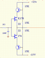
I do not know Nelsons set-up other than that it is SE without source resistors but here is what I am using. I have tried a number of different variations on the theme but yhis is the one i like best so far. I need alot of swing and this one delivers.
Anders
Hi,
I do not know Nelsons set-up other than that it is SE without source resistors but here is what I am using. I have tried a number of different variations on the theme but yhis is the one i like best so far. I need alot of swing and this one delivers.
Anders
Attachments
mlloyd1 said:anything you can share at this point on the differences in the distortion spectra for these buffers built with or without source resistors?
Actually that's the most interesting part - not the source resistors
but the spectra.
The piece will be done shortly, however I have created it without
deciding on a destination for it.
😎
Re: Buffer topology
bappe;
thanks for sharing. i have done something somewhat similar myself.
i am curious to know if there was any reason you choose to cascode the current sink the way you did using the 2SA970 versus using another 2SC2240?
mlloyd1
bappe;
thanks for sharing. i have done something somewhat similar myself.
i am curious to know if there was any reason you choose to cascode the current sink the way you did using the 2SA970 versus using another 2SC2240?
mlloyd1
bappe said:
I'm on my cellphone so i'll keep it short. The idea is to lower the voltage swing over both jfet's in a simple and thermally stable way. I can elaborate a bit more around this when i get back to my pc.
Anders
Anders
What's the bipolars for? It should work with drains straight to rails?
This might explain it - scroll down to the section Super Symmetrical Cathode Follower : http://www.tubecad.com/2007/04/blog0104.htm
At least for triode buffers it should be better to bootstrap the cathode follower so that it sees a constant plate to cathode voltage. But I'm not sure yet if this applies to the same degree to JFETs.
They allow for more swing with higher supply rails and should improve bandwidth by reducing non-linear capacitance of the j-fets.
If that is the intention, will put capacitor//to inner 15k (for bootstrapping towards output node) perform better?
i understand why cascoding is done. i'm asking why it was done a certain way.
just in case my question wasn't clear ...
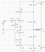
refer to the two buffer schematics in the attached schematic.
why cascode the current sink (j2) with a pnp (q4) instead of cascoding the current sink (j4) with npn (q3).
just in case my question wasn't clear ...
refer to the two buffer schematics in the attached schematic.
why cascode the current sink (j2) with a pnp (q4) instead of cascoding the current sink (j4) with npn (q3).
Attachments
Hi Michael,
I think the second method might be better (cascoding the current source).
Maybe Mr.Pass could shed some light on this............but then again, in the case of the B1, cascoding might not be an improvement besides you can run into stability issues when you cascode.
I can't wait for the article to come out............maybe if we found some way to prod Mr.Pass to get it out sooner.😀
Jam
P.S. Mr.Pass wrote a great article on cascode amplifier design. Here is the link
http://passlabs.com/pdf/articles/cascode.pdf
oops, sorry, in the schematic i posted, i forgot the "bootstrap" connection that bappe was using (the vds of the jfets is not fixed)
please remember there is a connection between the output and junction of r1 and r11 for the left hand circuit and a connection between the output and the junction of r6 and r8 for the right hand circuit.
i'll fix the schematic when i get to my other computer.
of course, we could always argue about the virtues of fixed versus telescopic cascodes ...
😀
mlloyd1
mlloyd1 said:i understand why cascoding is done. i'm asking why it was done a certain way.
just in case my question wasn't clear ...
refer to the two buffer schematics in the attached schematic.
why cascode the current sink (j2) with a pnp (q4) instead of cascoding the current sink (j4) with npn (q3).
corrected schematic attached
mlloyd1
mlloyd1
mlloyd1 said:oops, sorry, in the schematic i posted, i forgot the "bootstrap" connection that bappe was using (the vds of the jfets is not fixed)
please remember there is a connection between the output and junction of r1 and r11 for the left hand circuit and a connection between the output and the junction of r6 and r8 for the right hand circuit.
i'll fix the schematic when i get to my other computer.
of course, we could always argue about the virtues of fixed versus telescopic cascodes ...
😀
mlloyd1
Attachments
review
Look here too : http://www.enjoythemusic.com/magazine/equipment/0708/first_watt_b1_preamplifier.htm
Look here too : http://www.enjoythemusic.com/magazine/equipment/0708/first_watt_b1_preamplifier.htm
Fantastic . I am going to build in perforboard p2p this piece .
I have a question that raises now . My F3 is coupled to a buffer input stage like the Buffer for Blues or like the Zen V4 .
Is it the time to leave it for this loveable B1?
Will I have better satisfaction with B1 ?
Thanks
I have a question that raises now . My F3 is coupled to a buffer input stage like the Buffer for Blues or like the Zen V4 .
Is it the time to leave it for this loveable B1?
Will I have better satisfaction with B1 ?
Thanks
Great article! Finally get to use those surplus 1 meg resistors! 😀
Mouser has the J113. Not seeing 2sk170, LSK170 or 2SK370.
http://www.mouser.com/Search/Refine.aspx?Ntt=512-J113
This jfet ok?
thx,
Vince
Mouser has the J113. Not seeing 2sk170, LSK170 or 2SK370.
http://www.mouser.com/Search/Refine.aspx?Ntt=512-J113
This jfet ok?
thx,
Vince
Some time ago the Linear systems so kindly sent me 5 lsk389 as samples . I think I will use 2 of them.
😎
😎
- Home
- Amplifiers
- Pass Labs
- B1 Buffer Preamp