JFET push-pull
Have you considered trying a dc coupled version of the B1?
- Is it better?
- How about availability of critical components?
- Are there good substitutes?
I have built both single ended B1 and B1 rev2. But with different power supplies and attenuators. B1 had a switcher and the psu from the article. Rev 2 had a fancy linear super reg.
My preference was for regular B1. Push pull B1 was a little bit too ruthless and sterile for my tastes. With a warm power amp it might be ok. I don’t know if it’s the coloration of the caps in rev 1 or the single ended nature but rev1 just sounded more musical to me.
But I prefer KORG b1 over either of them.
It's gonna mostly depend on the amp that follows after it.
If you had an ACA then most likely a B1 rev 2 (or rev 1) would be most preferable. If you had a Sony V2, then most likely a B1 Korg would be preferable.
Of course everyone's tastes are different as well as the speakers they might own. So this is never a clear cut answer.
If you had an ACA then most likely a B1 rev 2 (or rev 1) would be most preferable. If you had a Sony V2, then most likely a B1 Korg would be preferable.
Of course everyone's tastes are different as well as the speakers they might own. So this is never a clear cut answer.
Channel imbalance
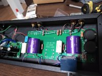
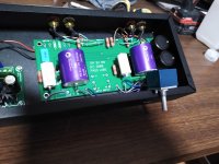
I built my B1 a few months back and have been very happy with it. But while trying to setup an active crossover the other day, I measured less than half the output voltage on the left channel than on the right. I've double checked all my solder joints and the correct value and placement of all parts. Everything looks right. So I'm a little stumped. Funny thing is I've never heard this imbalance while using the B1, which at half the output seems like it would be apparent. Has anybody had a similar issue?
I built my B1 a few months back and have been very happy with it. But while trying to setup an active crossover the other day, I measured less than half the output voltage on the left channel than on the right. I've double checked all my solder joints and the correct value and placement of all parts. Everything looks right. So I'm a little stumped. Funny thing is I've never heard this imbalance while using the B1, which at half the output seems like it would be apparent. Has anybody had a similar issue?
thirdcomplex. Just to be sure, did you use the same source for both channels? Are you sure the imbalance is in the B1 and not in the source?
Yeah, I probably should have mentioned that. I did try different sources with the same results. Tried swapping cables too
Swap the volume control wiring L/R channel assignment.
If the imbalance stays in the same channel, it's in the boards, if it changes sides, the volume control is the issue.
If the imbalance stays in the same channel, it's in the boards, if it changes sides, the volume control is the issue.
Quote:
"Swap the volume control wiring L/R channel assignment.
If the imbalance stays in the same channel, it's in the boards, if it changes sides, the volume control is the issue."
Great advice.
Blue ALPS are known to have sometimes small and sometimes (many more times) big channel disbalance.
Worth keeping in mind.
After I posted earlier I took some measurements trying to track down the problem. Playing a sine wave through the B1 with the pot maxed I measured full voltage being passed for both channels at the pot pads on the board. I measured full signal at R102,202 as well. At the output caps I measured half voltage with the left channel. The output caps are so big I can't measure at the fet pins. And with the way I have things wired up I would have to desolder the rca connections to remove the board from the case. This was my first diy electronic project. I'm thinking I may have damaged the fets when I soldered them
if you measure voltage at inside pin of output cap, ref. to gnd, that could give some clue of state of JFets
though, logic sez it's Jfet(s), according to your last post
though, logic sez it's Jfet(s), according to your last post
Voltage measured at the input lead of the output caps shows half the input voltage for the left channel
- Home
- Amplifiers
- Pass Labs
- B1 Buffer Preamp