
When driving loads 2-5K I actually ended up using 150-226R after initially trying out 100R and lower.
Maybe it's time to check again with the new higher input impedance power amps ...
Noted that ZM went as low as 22-51R (37R4)
Maybe it's time to check again with the new higher input impedance power amps ...
Noted that ZM went as low as 22-51R (37R4)
if talking about Fool-proof resistor - series one in output - ZM is using none ( so , me being biggest fool)
means - in my buffers there is no series output resistor, squeezing last available Ohm out ..... not so important when driving 10K , but when going down, every Ohm is important, if for nothing else then for my nice and cozy nap
If I did leave in place some, while posting edited Papa's schematic, that was just mild editing - decrease its value instead of deleting/shorting
Last edited:

Chassis info
I put this question in a separate 3d because it is nothing to do with my previous.
I'd like to emulate the look of the FW B1 preamp
Does anybody knows:
1. size of the enclosure
2. I have to say I particularly like to two minimal front knob. There are a number like that available online, but with several different size. Can somebody tell me the (base) diameter and height of those used on the FW B1 chassis?
Tnx
P
I am considering to buy
the "B1 PCB plus 4 matched JFETS" package from PassDiy
I searched on the website but I didn't get the following:
1. what is the board physical size?
2. is that board doing input selection like the official "Pass B1 preamp"?
The board is about 7.5" by 3.25", so about 190mm x 80mm.
The board itself does not do any switching, though it provides for two inputs and has connectors for a DPDT switch (or something similar). If you want more inputs, you can bypass the connections to the board and connect your RCA jacks directly to the switch, and from their either back to the board or directly to the pot. (Probably you do still want the 1M resistors to ground which are at the inputs on the board, but you can arrange that some other way.)
I am considering to buy
the "B1 PCB plus 4 matched JFETS" package from PassDiy
I searched on the website but I didn't get the following:
1. what is the board physical size?
2. is that board doing input selection like the official "Pass B1 preamp"?
Tnx
P
2. Yes
Please explain this
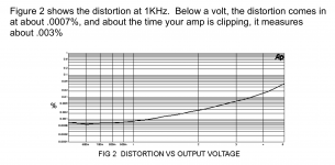
Okay. I see that B1 is a Class A buffer preamplifier. I emphasize that Class A because it is essential here. The design is also such that there is no long feedback. I would expect that the relative distortion would continue decreasing as long as signal voltage keeps decreasing. But what do we see? There is a minimum at 600 mV.
What is this phenomenon?
Attachments
Interesting, I did not measure it, but had a clear impression of increased distortion and overloading the B1 when running the low values.
I have mainly been using it with the volume cranked to max, actually missing 6-12dB gain.
I have mainly been using it with the volume cranked to max, actually missing 6-12dB gain.
if talking about Fool-proof resistor - series one in output - ZM is using none ( so , me being biggest fool)
means - in my buffers there is no series output resistor, squeezing last available Ohm out ..... not so important when driving 10K , but when going down, every Ohm is important, if for nothing else then for my nice and cozy nap
If I did leave in place some, while posting edited Papa's schematic, that was just mild editing - decrease its value instead of deleting/shorting
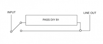
Thanks - at the input or both in and out? Would love to just have one switch as a total bypass if possible.
Pardon the crude drawing and the likely idiotic question, but if I want to add a complete circuit bypass switch for the B1 would it be as simple as this?
......bypass switch at the output:
switch between B1 output and bypass line.
Ahh, so instead of placing the switch before the B1, place it after? If so, that's a piece of cake.
Thanks - at the input or both in and out? Would love to just have one switch as a total bypass if possible.
Bypass input and output of B1 buffer.
Hi, everyone,
I've recently built a balanced B1 pre-amp, and was completely blown away by it. It's about as good, in my system, as my XP-20, and in some ways is even better. So I've decided to build an 'upscale' version, with better (or at least more expensive) parts. I'm using Vishay ZFoils for the 1K resistors; Jentzen Cross-Caps for the coupling caps; and Elna Silmics for the electrolytics. For the 1M and 221K caps, I've used the best I can find, e.g., Takmans REYs. Those look less critical, yes?
I've recently built a balanced B1 pre-amp, and was completely blown away by it. It's about as good, in my system, as my XP-20, and in some ways is even better. So I've decided to build an 'upscale' version, with better (or at least more expensive) parts. I'm using Vishay ZFoils for the 1K resistors; Jentzen Cross-Caps for the coupling caps; and Elna Silmics for the electrolytics. For the 1M and 221K caps, I've used the best I can find, e.g., Takmans REYs. Those look less critical, yes?
- Home
- Amplifiers
- Pass Labs
- B1 Buffer Preamp