That is what I needed.
While i am at it, I am using the 220K you specified in your LIGHTSPEED volume control.
Is that about as high as one should go?
Is there an ideal? Is this something that would vary with system? As I would expect ...
THANKS, ZM
While i am at it, I am using the 220K you specified in your LIGHTSPEED volume control.
Is that about as high as one should go?
Is there an ideal? Is this something that would vary with system? As I would expect ...
THANKS, ZM
I've been thinking about building a passive pre for quite some time and just now i read about the B1 buffer pre which looks like a very nice project. Of course I have a few questions for the people on here who know more about electronics than I do (probably most people 🙂.
1.) I was planing on building a super simple passive with just a volume control and a selector switch. (signal in --> selector switch --> pot --> signal out). Now as far as I know there wouldn't be an impedance issue between my phono pre, passive and power amp using a 20k pot. So here's the question: Assuming no buffering is actually needed, would there be any benefits (or drawbacks) in using a B1 over the mentioned "super simple" passive?
2.) people seem to use a variety of different caps for the B1. Will the caps actually affect the sound or is it just a matter of taste or a matter of what spares people have in their tool box 🙂 ?
3.) it seems the B1 uses linear pots instead of log pots. why is that?
4.) the input impedance is determined by the resistance of the pots used - but what's the output impedance of the B1?
Thanks,
Michi
I have an answer to question 1 and maybe question 2. I have tried a simple passive, a B-1, and maybe a dozen preamps with gain over the years. In my system, the B-1 sounded "better" than the simple passive, and better than the preamps with gain. I use tube amps, generally with 50-100k ohm input resistance. If you are using a CD player, tuner or other source with more than 1 volt output, you might not need any more gain. As far as coupling caps are concerned, I tried different types and did not find a preference. None of them were $$$$, but I did try metalized polypropylene, film and foil, and paper in oil, and concluded that the differences were insignificant. As always, YMMV. I liked mine so much, I built one for my son's system.
Hi Mixi,
I’ve used “super simple, just a pot” instead of a preamp in the past because my components should work well together, but the sound was alway kind of wan and thin and just didn’t sound as great as I expected. Tried the buffer, and the system sounded a lot more solid. So it worked for me!
I’ve used “super simple, just a pot” instead of a preamp in the past because my components should work well together, but the sound was alway kind of wan and thin and just didn’t sound as great as I expected. Tried the buffer, and the system sounded a lot more solid. So it worked for me!
3.) it seems the B1 uses linear pots instead of log pots. why is that?
4.) the input impedance is determined by the resistance of the pots used - but what's the output impedance of the B1?
Thanks,
Michi
Thanks a bunch! Anyone have answers to my other two questions 🙂 ?
lin or log pot.........everybody has his personal preference (lin: more precisely, less abbreviation between the two channels;
log fits subjectively better to the "loudness properties" of the ears );
a buffer amp has a low output impedance, ideally near zero ohm.
in the B1 it is dertermined by R104/R204 = 1kOhm in the signal path......
log fits subjectively better to the "loudness properties" of the ears );
a buffer amp has a low output impedance, ideally near zero ohm.
in the B1 it is dertermined by R104/R204 = 1kOhm in the signal path......
seems like some people use batteries to power the B1. are there any advantages or disadvantages (except the obvious like having to change the batteries) in using batteries instead of a mains connection? how long will the b1 run on say to 9V batteries in series?
regarding the vol pot. isn't it common practice to use log pots for audio use? any special considerations why one would use linear pots in the b1?
regarding the vol pot. isn't it common practice to use log pots for audio use? any special considerations why one would use linear pots in the b1?
I have few question about the original B1:
1. Can I omit the C100 and C200 input caps if my source (DAC) is direct-coupled?
2. If yes, do I need to change value of other components ?
Thanks,
Trung
1. Can I omit the C100 and C200 input caps if my source (DAC) is direct-coupled?
2. If yes, do I need to change value of other components ?
Thanks,
Trung
Hi, Would it be possible to increase R1 a bit in order to lower PSU voltage?
I will be using 20V PSU, so I was aiming towards recommended voltage, especially if BF862 would be in question.
If possible, is there a need for changing C1 also, since R1 and C1 are working/acting as noise filter?
Thanks
I will be using 20V PSU, so I was aiming towards recommended voltage, especially if BF862 would be in question.
If possible, is there a need for changing C1 also, since R1 and C1 are working/acting as noise filter?
Thanks
Hi, Would it be possible to increase R1 a bit in order to lower PSU voltage?
I will be using 20V PSU, so I was aiming towards recommended voltage, especially if BF862 would be in question.
If possible, is there a need for changing C1 also, since R1 and C1 are working/acting as noise filter?
Thanks
Isn't the recommended voltage range 18-24V? So i guess 20V should be perfectly fine. On another forum people mentioned using it with power supply as low as 9V with good results.
I run my B1 off a symmetrical power supply with matched FETs, and did away with the input and output caps. Output offset is non-existent. Very pleased with the result.
I was wondering whether anyone has tried different JFETs, as the properties due to the buffer character may be a bit less critical compared to circuits with more than unity gain. I have procured some CPH3901's so will give them a try soon.
I was wondering whether anyone has tried different JFETs, as the properties due to the buffer character may be a bit less critical compared to circuits with more than unity gain. I have procured some CPH3901's so will give them a try soon.
I have a B1 with 2sk369-GR.
It's been running for a good 3-4 years now. Magnificent!
Also ACA with 2sk369-BL (actually 5 channels). All good.
Soon will try it with the old 2N3819 (horror, horror!!!) cause I have hundreds of them.
It's been running for a good 3-4 years now. Magnificent!
Also ACA with 2sk369-BL (actually 5 channels). All good.
Soon will try it with the old 2N3819 (horror, horror!!!) cause I have hundreds of them.
It could be, but I guess if you parallel a few that can change.
Of course keep an eye on the Id and dissipation, maybe cascoding will help.
2n3819 is an exercise for the sake of it, as I said I have many of them and would prefer to use them one way or another than discard them.
Of course keep an eye on the Id and dissipation, maybe cascoding will help.
2n3819 is an exercise for the sake of it, as I said I have many of them and would prefer to use them one way or another than discard them.
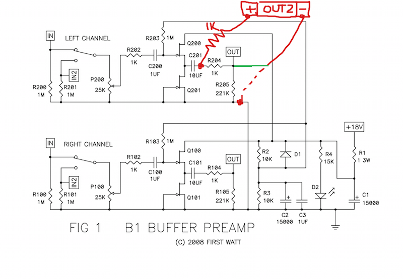
I have this image in my archive for connecting a second output. I'm wondering why the negative line is not connected to the same point as the first output's? (shown in green in the second image)
In the first image, Output 1 has a 221K resistor to ground, but Output 2 doesn't.
Can someone shed some light, please?

In the first image, Output 1 has a 221K resistor to ground, but Output 2 doesn't.
Can someone shed some light, please?
Attachments

Both are incorrect, duplicate R204 & R205 for the second output.
I was a little too quick, you can use the first one, it's just me, I would add R205.
Thanks Itsmee. I had confirmation from a different source that the first one is correct.
However, your suggestion to add R205 makes sense. Easy to check with and without, though.
However, your suggestion to add R205 makes sense. Easy to check with and without, though.
B1 Buffer, BF861B + Baffle step filter
If anyone's interested, I just completed this circuit, a baffle step filter sandwiched between two B1 type stages. Front and back of circuit same as B1. JFET's chosen for about 9mA Idss bottom, 10mA Idss top. For 20V, well within the maximum power and voltage specs for BF861B. Initial impressions sounding very good c/f existing LSK170-based B1. 4dB correction seems to be fattening the sound of my ACA/Coniston's 4-foot off rear walls nicely. Need to do much more listening now.
If anyone's interested, I just completed this circuit, a baffle step filter sandwiched between two B1 type stages. Front and back of circuit same as B1. JFET's chosen for about 9mA Idss bottom, 10mA Idss top. For 20V, well within the maximum power and voltage specs for BF861B. Initial impressions sounding very good c/f existing LSK170-based B1. 4dB correction seems to be fattening the sound of my ACA/Coniston's 4-foot off rear walls nicely. Need to do much more listening now.
Attachments
- Home
- Amplifiers
- Pass Labs
- B1 Buffer Preamp