OK
many thanks
need to buy a few parts now
I have small 2x22Vac C'core trafos, so I will use regulated supply
and maybe a bunch of small caps after that
many thanks
need to buy a few parts now
I have small 2x22Vac C'core trafos, so I will use regulated supply
and maybe a bunch of small caps after that
Tinitus
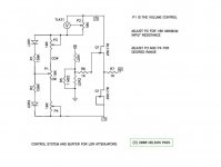
I havent built this but the 150k resistors might make it hard to use. I suggest try trimmers there first, then replace with resistors. Good luck. Looks like a fun and educational project.
PS when you first fire it up please have those trimmers at full resistance, then with a DMM on the resistors side of the LDR.. turn the trimmer down til you get desired resistance of 40R on shunt at min volume and no less than 40R on series at max volume. Then you know you are safe and not burning the LED in the LDR.
If you can adjust overall Rtot of your LDR attenuator I suggest trying to go as low as you can and still have whole circuit stable. I enjoy 6k very much. Super detail and transparency down there.
Uriah
hey, Uriah, my LDR expert man
are you sure it works like the usual LDR curcuit
somehow it looks different to me
att 'voltage' pot looks to me more like a balance pot
would the load voltage to LED's not be more like the difference between positive and negative
or something like that
are you sure it works like the usual LDR curcuit
somehow it looks different to me
att 'voltage' pot looks to me more like a balance pot
would the load voltage to LED's not be more like the difference between positive and negative
or something like that


Why not parallel the output of your transformer, and use a standard LM317- derived regulator? You only need to get the output voltage down to 22-23 volts.
Why not parallel the output of your transformer, and use a standard LM317- derived regulator? You only need to get the output voltage down to 22-23 volts.
ah, yes, I was thinking maybe adjustable would be better with the higher voltage trafo 🙄
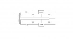
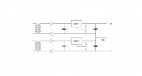
using double secondary(not CT), and double bridge, I can stack two LM317, side by side, to form the +/- supply
this would be ok, right ?
Attachments

when you use a dual secondary transformer, all the options shown in posts 2985, 2987, 2988 work.
The 78xx series of regulators are still available and do work. An ordinary 317 without the regulation improvements added performs about as well as a 78xx reg.
The 78xx series of regulators are still available and do work. An ordinary 317 without the regulation improvements added performs about as well as a 78xx reg.
If you use a full-wave bridge your AC will be smoother and the regulators will be under an easier load. Don't forget to use big heatsinks if you are planning to throw away a lot of volts.
great
hmmm, I understand current could be problem
smaller trafos may be needed
oh, yes, full bridge, ofcourse
just a lazy drawing
seems like there are more tricks around, diodes, leds, etc
well, its always nice to learn something useful
hmmm, I understand current could be problem
smaller trafos may be needed
oh, yes, full bridge, ofcourse
just a lazy drawing
seems like there are more tricks around, diodes, leds, etc
well, its always nice to learn something useful
I hope this is ok with Nelson
Better here than in the Lightspeed thread, where it probably got lost...
😎
hmm, new trafos are too expencive
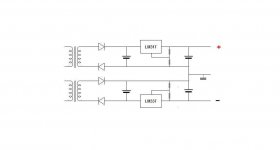
looking at 7815/7915 regs
rated at 1A and 35Vdc in, they should be able to cope with my trafos
maybe some CRCRC will help
and 'inrush' thermistrs
Tinitus,
I see that the current through the LDR is limited by the 150k resistor. I have not used 15V and a 150k resistor but I have used 12.5V and a 22k resistor and on that will yield a min value of LDR resistance around 250R. I dont see the circuit linked here http://www.diyaudio.com/forums/pass-labs/124889-b1-buffer-preamp-299.html#post2602176 in post 2981 as being able to go very low in LDR resistance so your min volume will be loud.
Uriah
I think the reason it got lost, which it really did, is simply because folks reading that thread are a bit anti active preamplification and also they are looking for an extremely simple circuit when they get there. The circuit has active circuitry in the signal and maybe is a bit intimidating, I'm not sure. Probably has a lot more to do with the fact that they were looking for passive to start with.
I have used gain after the Lighter Note 3 times. DCB1, tube gain stage and opamp gain stage. I liked them all very much and it adds to the dynamics to have gain after the LDRs. Dont put gain before them if you can avoid it as higher voltage across the resistor side of the LDRs develops noise. Amplification later is fine. I am using a headphone amp after them right now and really enjoying it. So its Source > LDRs> HeadAmp> Amp. Nothing against actives in my philosophy, even if I am a bit passive aggressive 🙂
While dynamics were improved the soundstage got wider and lost depth in one gain experiment. The gain stage obviously needs to be as good as the passive stage. I think this circuit would be a wonderful project and super simple to implement.
Uriah
Last edited:
hmm, new trafos are too expencive
looking at 7815/7915 regs
rated at 1A and 35Vdc in, they should be able to cope with my trafos
maybe some CRCRC will help
and 'inrush' thermistrs
With the ultra low amount of current you will be using I think you could get away with resistors rather than thermistors.
CRCRC will be good for sonics. LDRs like a great power supply with decent capacitance but after the regulators use about 100uf and then on the LDRs put 10-100uf but NO MORE. More will mess with the way they increase/decrease volume.
Another thing about capacitance on the LDRs.. If you want to shut off your preamp before you shut off your amp, for whatever reason, you want to stick more capacitance right on the shunt LDRs so that the series go dark first and fast vs the shunts going dark last and slow or your volume will increase like crazy for a second or two. The Jfets losing power might stop this from happening though unless the Jfets also have a bunch of capacitance on them.
Uriah
Last edited:
I'm listening 
with support like this I'm confident it will work, eventually 😉
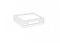
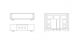
now thinking about layout, and what kind of box to order
with support like this I'm confident it will work, eventually 😉
now thinking about layout, and what kind of box to order

- Home
- Amplifiers
- Pass Labs
- B1 Buffer Preamp