Hi Jim,
This is the one:
Préamplification - Contrôleur de volume stéréo à commutation de résistances
Cheers!
This is the one:
Préamplification - Contrôleur de volume stéréo à commutation de résistances
Cheers!
If i understand correct what you want to do, then connect the relay volume pot to the input selector as you would normally do and then connect the input selector to one of the B1 input as in the picture a couple of posts before. You will then have to put jumpers at the B1 board at the place where the pot would normally connect. Jumpers can go like this: InR to OutL and InL to OutR
Here 3 different version of B1 we made ...
The latest version we made ... this proto have near 1500$ just in parts ...
Mundorf Silver&Gold&Oil 1k and 10K
Resistor Vishay the top list
DACT volume control (the top list)
Battery 5000ma 22.2v LiPo
RCA Connector WBT NextGen Gold (I have Silver too but not tried yet)
Batterie connector DIN
Ground wire OCC 7N copper in one big segment
Solder Mundorf
* this is VERY good indeed!
A very very good version here ... A WAY better to the original proto...
Original proto (150$) including the interconnect.
* Not bad but on our system, it's a bit agressive.
The latest version we made ... this proto have near 1500$ just in parts ...
Mundorf Silver&Gold&Oil 1k and 10K
Resistor Vishay the top list
DACT volume control (the top list)
Battery 5000ma 22.2v LiPo
RCA Connector WBT NextGen Gold (I have Silver too but not tried yet)
Batterie connector DIN
Ground wire OCC 7N copper in one big segment
Solder Mundorf
* this is VERY good indeed!
An externally hosted image should be here but it was not working when we last tested it.
A very very good version here ... A WAY better to the original proto...
An externally hosted image should be here but it was not working when we last tested it.
Original proto (150$) including the interconnect.
An externally hosted image should be here but it was not working when we last tested it.
* Not bad but on our system, it's a bit agressive.
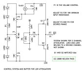
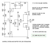
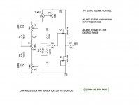
this 'old' LDR/buffer scheme by Nelson Pass use sk170 and sj74
wonder if anyone knows how to convert it to the B1 buffer 😕
Old?
Peice of cake!
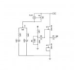
I might even have a dwg by the master himself(at home)? Basically just put the bottom transistor into a current source configuration and change it to the N type device. I guess some of the single endedness of the B1 needs to be addressed as in "symetrical B1 Buffer" thread.
this 'old' LDR/buffer scheme by Nelson Pass use sk170 and sj74
wonder if anyone knows how to convert it to the B1 buffer 😕
If you have already built it, try this
Attachments
piece of cake?
would be nice if it were
Itsmee, current source with N device, suggested by flg, is that what you are drawing ?
no, nothing built yet
but I urgently need a preamp
and I have the fets, and matched LDR
well, I also have both "symmetrical B1" boards
but sj74 are rare
would be nice if it were
Itsmee, current source with N device, suggested by flg, is that what you are drawing ?
no, nothing built yet
but I urgently need a preamp
and I have the fets, and matched LDR
well, I also have both "symmetrical B1" boards
but sj74 are rare
Thanks 6L6. I got the R-core from junked test equipment. I believe you can find some on e-bay. Good luck!
Alf
Alf
ok, i'll skip the LDR
seems pointless anyway
with a source slector there will still be a switch in signal path
and resistors too
guess I can just as well use Broskies new mono attenuator
hmm, they come with print boards
maybe I can find a place for the jfets on there too 🙄
seems pointless anyway
with a source slector there will still be a switch in signal path
and resistors too
guess I can just as well use Broskies new mono attenuator
hmm, they come with print boards
maybe I can find a place for the jfets on there too 🙄
no, nothing built yet
The drawing is a 2SK170 and a 2SJ74, but seeing as you haven't built anything yet, just use 2x 2SK170 as per the B1
..... just use 2x 2SK170 as per the B1
do you mean use the entire B1 schematic with +18/0 volt ?
but then the integration of LDR will be different
the way Nelson's suggest, it appears to me like it depends on symmetric +/- supply
😕

one thing I do not understand
why is there only voltage regulator on positive to 'source LDR'
'shunt' LDR connects direct to negative voltage
why is there only voltage regulator on positive to 'source LDR'
'shunt' LDR connects direct to negative voltage
Do you mean source & shunt LEDs?
The LDRs are connected to the audio signal only.
I meant the controller LED's
hmm, I thought the LDR going to ground was called the shunt LDR
ah, ok, that would be both source LED and shunt LED(yes?)
but I don't understand the power going to the controller LED's ?
- Home
- Amplifiers
- Pass Labs
- B1 Buffer Preamp