Yes go ahead and reassemble the PS board along with the added bleed resistors. If you want to include a picture of the resistors after you install them just to check that would be good.
Okay, so R (bad) channel measures 0.6 ohm from point #2 to pos rail on PS cap. However, I just get a 00.00 ohm reading on the L channel pos rail of PS cap ... of course, the black probe is still on point #2 on R channel.
I have to get ready for work, so will be offline for an hour or two. I can get some measurements done at lunch. I'm two hours behind you KC.
Matt
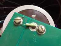
If this becomes a permanent mod, I'll find some ring terminal connectors so that the screw is flat with full contact ... resistors can be soldered to the tabs.
I have to get ready for work, so will be offline for an hour or two. I can get some measurements done at lunch. I'm two hours behind you KC.
Matt
If this becomes a permanent mod, I'll find some ring terminal connectors so that the screw is flat with full contact ... resistors can be soldered to the tabs.
Attachments
Last edited:
The resistors look good. Now with the resistor leads you've got an easy spot to clip your negative side alligator when you need to attach it to ground.
I'm not certain what you were measuring when you listed 00.00ohms in the good channel reading in your last post? Did you measure point #2 on the good channel to PS + DC rail?
I'm not certain what you were measuring when you listed 00.00ohms in the good channel reading in your last post? Did you measure point #2 on the good channel to PS + DC rail?
Measuring ohm value across point #2 and Pos rail on PS board for L channel has different behavior on DMM.
The bad channel (R) is quick to rest on it's value. But the L channel starts off around 1.5k ohms and goes up around 27k ohms and moves down a little and up ... I can't get it to rest on a "final" value. But it is under 1 ohm.
Based on the difference in getting a reading, there is something different (as we know) between both channels.
If we go back and think about the fact that when I took the amp into the tech, both channels were working and I had wonderful sound. I just wanted it biased. I personally think that one of two things happened. If I'm generous in my attitude ... something in the R channel failed during his testing. If I'm cynical, I'd say he didn't know what he was doing, or slipped and did something to cause the problem. The only other thing I can think of is that after my last time of listening to the amp, and before taking to him, he told me to pull the fuses, inspect and put back in, even though I was getting shorting/sparking when putting fuses back, since the caps were holding a charge.
I had a similar experience while reinstalling a fuse after an adjustment that led to the demise of a well matched set of inputs. Those big caps can hold a charge for quite some time.
The result was an increase in dc offset to a point where the amp needs replacement parts.
A 68k resistor across the terminals of the large caps is a good way to reduce the chances of making these mistakes.
The result was an increase in dc offset to a point where the amp needs replacement parts.
A 68k resistor across the terminals of the large caps is a good way to reduce the chances of making these mistakes.
So you are saying that if I keep this amp ... ie, can fix it for reasonable money ... I should swap the resistors out for 68k ohm, 2-4 watt? Or just for testing, to account for possible higher dc offset from PS caps?
That Rising resistance reading implies capacitive charging in the good Channel and doesn't make sense because it should be a direct short measuring less than 1 ohm from the positive dc rail to point #2 on either board.
You put all 4 fuses back in the PS board correct?
Is the wire harness plug connected for both channels?
You put all 4 fuses back in the PS board correct?
Is the wire harness plug connected for both channels?
68k resistors are fine if you want to wait 15min for your caps to fully discharge. Most manufacturers use values < 10k ohms so the caps discharge at a reasonably quick rate.
You put all 4 fuses back in the PS board correct?
Is the wire harness plug connected for both channels?
Yes on both counts.
Now the R channel is measuring 133k ohms.
L channel is measuring anywhere from k ohms to 10M ohms ... it depends on how I get the ground probe on point #2 (LED)
L channel is measuring anywhere from k ohms to 10M ohms ... it depends on how I get the ground probe on point #2 (LED)
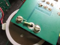
So clip your minus lead alligator to the + DC rail screw (use the resistor lead you just added). This is the big red arrow on the PS board picture I posted before.
Now use the red lead to measure point #2.
Now use the red lead to measure point #2.
Red lead for point #2 on both boards. It should be under 1ohm and it should not rise up then fall back down.
So clip your minus lead alligator to the + DC rail screw (use the resistor lead you just added). This is the big red arrow on the PS board picture I posted before.
Now use the red lead to measure point #2.
8M ohms and falling ...
Amp is NOT powered up.
Red lead for point #2 on both boards. It should be under 1ohm and it should not rise up then fall back down.
8.5k ohm and slowly rising.
Okay I believe the red wire going in the bottom of the CHANNEL board from the PS BOARD is the + DC rail volts. Leaving your ground clip in the same location as before use your red probe to measure where the red wire enters at the bottom of the channel board. How mamy ohms do you have here? If its more than a few ohms pull the 3 pin power plug apart for that channel and measure the pin that the red wire goes to on the side going to the PS board. How many ohms?
Do you see what it is we're doing here? Effectively there should be a direct connection between the plus DC rail screw and point #2 on both channel boards. Imagine the voltage travels from the + DC rail screw through the fuse out the red wire through the 3 pin connector to the channel board and is then distributed to a few different components on the channel board. If you measure between any two points in that pathway you should measure less than an ohm if its connected properly.
I see what we are doing. 🙂
Pulled plugs to measure red wire coming from PS board. Ground probe on +DC rail screw ...
R = OL in M ohm (auto DMM)
L = .4 ohm
So it would appear the problem is from the power plug (R) to the PS board?
Pulled plugs to measure red wire coming from PS board. Ground probe on +DC rail screw ...
R = OL in M ohm (auto DMM)
L = .4 ohm
So it would appear the problem is from the power plug (R) to the PS board?
Last edited:
Check the red wire where it attaches to the connector pin. Sometimes they break and just the insulation holds them together.
- Status
- Not open for further replies.
- Home
- Amplifiers
- Solid State
- B&K ST-202 Plus :: hum