Very puzzling. I checked all the components for proper orientation/value and reflowed all the solder connections (just to be sure). Operation unchanged.There is a relay that switches the inputs when you go from SE to Bal and vice versa. Check the orientation.
If you leave the Bal input connected and then select SE button, how does it work then?
You could also check pin 13 of U1, that should switch between SE and Bal.
Jan
I traced the input signal across the board. The full applied signal was present at R5 (SE input) and R7 (Bal input). With Bal input selection, the attenuator kicks in and the signal at R7 is attenuated. With SE input selection, the attenuator remains at +18dB will full signal present at R5 (un-attenuated). In this case I was using ~7VAC input signal.
I also noticed that pin 3 of U4 (OPA2134) is very sensitive to contact by the scope probe when in SE input mode and contact will cause attenuation switching to occur, though not to proper levels.
Also there is a high level of DC at the SE output connector, about +10VDC at no signal dropping to about +5VDC when a 1VAC signal is output selecting the Bal input. Selecting the SE input, the SE output remains at +10VDC with no VAC output signal.
I checked the power supply voltages on the attenuation and control boards and there are proper for level and polarity (+/- 15V, +5V).
Very puzzling. I checked all the components for proper orientation/value and reflowed all the solder connections (just to be sure). Operation unchanged.
I traced the input signal across the board. The full applied signal was present at R5 (SE input) and R7 (Bal input). With Bal input selection, the attenuator kicks in and the signal at R7 is attenuated. With SE input selection, the attenuator remains at +18dB will full signal present at R5 (un-attenuated). In this case I was using ~7VAC input signal.
I also noticed that pin 3 of U4 (OPA2134) is very sensitive to contact by the scope probe when in SE input mode and contact will cause attenuation switching to occur, though not to proper levels.
Also there is a high level of DC at the SE output connector, about +10VDC at no signal dropping to about +5VDC when a 1VAC signal is output selecting the Bal input. Selecting the SE input, the SE output remains at +10VDC with no VAC output signal.
I checked the power supply voltages on the attenuation and control boards and there are proper for level and polarity (+/- 15V, +5V).
I'm starting to think suspiciously in the direction of the opamps while I wait to hear back from Jan. Luckily I socketed all the IC's when I built the boards. If I'm lucky I'll have suitable replacement op-amps to try if not exact replacements. Have to sift through my op-amp stash.
I'm starting to think suspiciously in the direction of the opamps while I wait to hear back from Jan. Luckily I socketed all the IC's when I built the boards. If I'm lucky I'll have suitable replacement op-amps to try if not exact replacements. Have to sift through my op-amp stash.
Wasn't the op-amps at fault. Turns out one of the two fuses was bad. Must have been bad out of the box since I've yet to even use the AutoRangerMkII yet. Luckily I'd socketed the fuses, so it was easy enough to swap the bad fuse out with a piece of wire for testing.
Sorry to trouble you Jan.
Mike Miller
No problem, well done!
BTW Anyone saw the Autoranger review in AudioXpress? Reviewer actually seems to like it and is very positive. He apparently needed a top of the line APx555B to find any distortion!
Jan
BTW Anyone saw the Autoranger review in AudioXpress? Reviewer actually seems to like it and is very positive. He apparently needed a top of the line APx555B to find any distortion!
Jan
No problem, well done!
BTW Anyone saw the Autoranger review in AudioXpress? Reviewer actually seems to like it and is very positive. He apparently needed a top of the line APx555B to find any distortion!
Jan
Thanks again. I did notice a small issue after jumpering out the bad fuse. On the 0.4V output .setting, the AutoRanger was dithering on attenuator settings at lower signal levels. As I increased or decreased the sinewave voltage level, the AutoRangerMkII would switch back and forth between two attenuation levels at certain input voltage levels like it could not make up it's mind. At the 1.0V output level setting this issue was not observed.
Since I plan to use the device at the 1.0V output level setting for my EMU-0404USB soundcard, I did not pursue any further investigations.
Have you seen this issue before? I may look into it more if I have some time.
Mike Miller
Hi Jan.
I took some time to look into the switching issue I am observing with my build of the AutoRangerMkII. I do not know if it occurs with other units as well, or is specific to my construction.
The behavior is as follows: At each signal level where the unit switches attenuation levels it will alternate back and forth between the two levels (ie: 0 and +6dB) at approximately 1-2 cycles per second. The OV and UN LED's flash as the internal relays cycle back and forth. This only occurs on the 0.4V output level setting, not the 1.0V setting. It occurs on both SE and BAL inputs.
The range of signal voltage over which this occurs is 5mV at the +18/+12dB point (signal from 70 to 75mV) and 370mV at the -18/-24dB point (4.53 to 4.90V). The issue occurs at all of the switch points at about the same relative spread of voltages. I measured the voltage ranges sweeping my sine generator from 50mV to 7.5V using 1kHz, but will not type them all in here for brevity.
Once the signal level moves away from the attenuation switch point, the unit maintains proper attenuation until the next switch point is reached. Basically it behaves like a Schmitt trigger on the inputs is needed on the 0.4V output setting. Perhaps this can be changed in firmware? I only guess, as I do not know how the attenuation switch points are managed by the unit. Or maybe this is a construction issue from when I assembled my unit. Otherwise it works fine now that I have replaced that defective fuse.
Mike Miller
Hi Mike, sorry to be so long in replying.
The AR switches up or down as the input RMS level reaches one of two limits. The value of those limits has two conflicting requirements. On te on hand, the 'window' between the two values must not be too large so that the output stays as close to the nominal value as possible.
OTOH, the limit must not be to small, to avoid that for instance it switches up, only to find that the upper limit is exceeded, switches down, only to find that the lower limit is passed, etc.
In your case, that limit may be just on the edge. I will review the values for a next update. If it really interferes with your measurements, let me know and I'll see what I can do. Ort I can send you a new version (see next post) to try out.
Jan
Last edited:
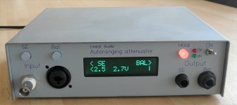
Several people have asked repeatedly for different nominal values than just 0.4V and 1.0V. I have updated the software to make it possible to select a value between 0.5V and 2.7V in 0.5V steps. The 2.7V is the max the existing hardware can handle.
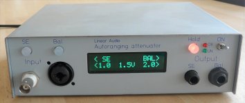
The procedure is similar to selecting one of the values in the current software: switch on the AR while keeping the Hold button pressed.
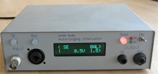
For the new software (ARII-2-sel) you now get a menu, preset to 1.5V. Using the SE and Bal buttons you can step through the menu to select the value you want.
Attached are some pictures (I'm not a photographer as you can see ...). The 1st is the value set when you switch on with Hold depressed (1.5V). The next two show the max and min values that can be selected. Selections are kept when you switch off, until you set them to a new value.
For those of you who want the new version, I can send a new chip for € 10 including flat shipping.
Jan
The procedure is similar to selecting one of the values in the current software: switch on the AR while keeping the Hold button pressed.
For the new software (ARII-2-sel) you now get a menu, preset to 1.5V. Using the SE and Bal buttons you can step through the menu to select the value you want.
Attached are some pictures (I'm not a photographer as you can see ...). The 1st is the value set when you switch on with Hold depressed (1.5V). The next two show the max and min values that can be selected. Selections are kept when you switch off, until you set them to a new value.
For those of you who want the new version, I can send a new chip for € 10 including flat shipping.
Jan
Attachments
Hi Mike, sorry to be so long in replying.
The AR switches up or down as the input RMS level reaches one of two limits. The value of those limits has two conflicting requirements. On te on hand, the 'window' between the two values must not be too large so that the output stays as close to the nominal value as possible.
OTOH, the limit must not be to small, to avoid that for instance it switches up, only to find that the upper limit is exceeded, switches down, only to find that the lower limit is passed, etc.
In your case, that limit may be just on the edge. I will review the values for a next update. If it really interferes with your measurements, let me know and I'll see what I can do. Ort I can send you a new version (see next post) to try out.
Jan
Not a problem Jan and thanks for getting back to me. The issue mentioned is a problem easily worked around by not parking a signal level right at one of those spots. Its more of annoyance that I thought you should be aware of and can perhaps adjust for in your next software revision.
I do seem to have a problem with the fuses. In my case the fuse on the SE input keeps blowing. I don't use the BAL input, so I don't know if that fuse would blow also. I would be on my 4th fuse, except that at the moment I have a breadboard jumper in the fuse socket to avoid the issue.
The AutoRangerII works fine in all other regards, so I think the assembly is okay. The largest amplifier I've tested with is ~ 60W (8ohm load), so I don't think the input signal level is excessive. The fuse just blows during normal usage.The size is correct I believe at 50mA. I'm thinking of perhaps trying a larger fuse, maybe 100mA, in case the 50mA size was just too small.
I measured the current (AC & DC) across the fuse socket during use and it's down in the 1mA range, so I'm not sure where the energy to blow the fuse is coming from. Perhaps an artifact from range switching. I measured the current with my bench DMM, but did not observe it on a scope, so I do not know if there are surges or pulses occurring.
Dear Jan,
a topological question. As I am currently designing a soundcard frontend for the purpose of acoustic measurements I had a second look at my Autoranger MK1.
As far as I have understood your attenuator topology (please correct me if I am wrong) the balanced attenuator output signals are directly fed to the balanced-out available at the TRRS jack. In consequence the resulting system-CMRR is also dependent on the balanced soundcard input attached to it.
Of course, this is not the case for the SE-out where the bal-unbal conversion is carried out inside the Autoranger.
Assuming that a typical consumer soundcard input has no precisely defined (and repeatable) CMRR specs... wouldn't it be more sophisticated to undertake a bal-unbal conversion in both cases in order to ensure constant common-mode performance?
What do you think about it?
Not a problem Jan and thanks for getting back to me. The issue mentioned is a problem easily worked around by not parking a signal level right at one of those spots. Its more of annoyance that I thought you should be aware of and can perhaps adjust for in your next software revision.
I do seem to have a problem with the fuses. In my case the fuse on the SE input keeps blowing. I don't use the BAL input, so I don't know if that fuse would blow also. I would be on my 4th fuse, except that at the moment I have a breadboard jumper in the fuse socket to avoid the issue.
The AutoRangerII works fine in all other regards, so I think the assembly is okay. The largest amplifier I've tested with is ~ 60W (8ohm load), so I don't think the input signal level is excessive. The fuse just blows during normal usage.The size is correct I believe at 50mA. I'm thinking of perhaps trying a larger fuse, maybe 100mA, in case the 50mA size was just too small.
I measured the current (AC & DC) across the fuse socket during use and it's down in the 1mA range, so I'm not sure where the energy to blow the fuse is coming from. Perhaps an artifact from range switching. I measured the current with my bench DMM, but did not observe it on a scope, so I do not know if there are surges or pulses occurring.
Mike that is strange. The only occasion I can think of is that the AR is at no attenuation or at gain, and you just throw 100V at it. It takes a few 100mS to range all the way down and in that time the protection diodes may conduct more than 50mA.
I don't remember of the top of my head what type of fuses they were, maybe try a slower blow one?
Jan
From the BOM:
693-0034.6001 Fuses with Leads (Through Hole) MSF 50mA 250V Fast Blow FUSE
I have blown a few fuses as well. I plan to use these next time I make an order:
693-0034.6602 Fuses with Leads (Through Hole) MST 250 50mA Time Delay/Slow Blow T 4.3
693-0034.6001 Fuses with Leads (Through Hole) MSF 50mA 250V Fast Blow FUSE
I have blown a few fuses as well. I plan to use these next time I make an order:
693-0034.6602 Fuses with Leads (Through Hole) MST 250 50mA Time Delay/Slow Blow T 4.3
From the BOM:
693-0034.6001 Fuses with Leads (Through Hole) MSF 50mA 250V Fast Blow FUSE
I have blown a few fuses as well. I plan to use these next time I make an order:
693-0034.6602 Fuses with Leads (Through Hole) MST 250 50mA Time Delay/Slow Blow T 4.3
I changed the fuse on mine (on the SE input, which is how I use the device) to a 100mA fastblow and will see how that works. It may be, as Jan observed, that I was changing the level of input signal too rapidly for the AutoRanger to keep up with switching attenuation levels.
From the BOM:
693-0034.6001 Fuses with Leads (Through Hole) MSF 50mA 250V Fast Blow FUSE
I have blown a few fuses as well. I plan to use these next time I make an order:
693-0034.6602 Fuses with Leads (Through Hole) MST 250 50mA Time Delay/Slow Blow T 4.3
Thanks Dennis, I'll make a note of that.
Jan
AudioXpress magazine has reviewed and tested my AR MKII. They needed to get an AP555B to be able to test it! I'm proud!
Jan
Jan
AudioXpress magazine has reviewed and tested my AR MKII. They needed to get an AP555B to be able to test it! I'm proud!
Jan
Congrats Jan. Very nice write up on a well designed project. I am coming to rely on mine more and more during testing amplifiers.
Jan, those are very impressive measurements, hats off.
I just do not understand this - in my OPA2134 measurements the H2 was at -130dBFs with fundamental at -6dBFs, THD -126dB which corresponds to the datasheet and measurements in http://www.ac-vogel.de/Download/Dow...act, no myths and THD measurement results.pdf. Measurements of the autoranger show the overall H2 at -145dBFs. Was OPA2134 used, or something newer (OPA1656)? Is the NE5534 in series with the signal (i.e. THD of two opams combined)? Thanks.
I just do not understand this - in my OPA2134 measurements the H2 was at -130dBFs with fundamental at -6dBFs, THD -126dB which corresponds to the datasheet and measurements in http://www.ac-vogel.de/Download/Dow...act, no myths and THD measurement results.pdf. Measurements of the autoranger show the overall H2 at -145dBFs. Was OPA2134 used, or something newer (OPA1656)? Is the NE5534 in series with the signal (i.e. THD of two opams combined)? Thanks.
Yes the se conversion adds a bit distortion. I don't remember which opamp was used in the attenuator/gain stage, I did experiment with the OPA2134 which I found wanting. I think it was the OPA1612.
The se converter was an LME49710.
Jan
The se converter was an LME49710.
Jan
- Home
- Design & Build
- Equipment & Tools
- Autoranger for soundcards