@jan.didden you have to clear your "PM" inbox I can not send you a PM because your postbox is full !!
And I did contact you via gmail
And I did contact you via gmail
I have purchased an Autroranger kit from Jan, very excited by this project. Mouser BOMs have been assembled, although they seem to be out of the Neutrik 3-pin XLR input, so that will have to be purchased elsewhere.
I am hoping I can save my poor fingers some trouble by buying a pre-made ribbon cable to connect the attenuator and control board. Could not find an appropriate part on Mouser, but this might do the trick, can be bought in a 4-inch length:
14-Pin (2x7) Female to Female 2.54mm-Pitch 14-wire IDC Flat Ribbon Cable | eBay
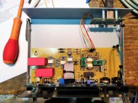
Unit complete
Hi everyone, a few days ago I finished assembling the MK2 Autoranger (20K ver.) I wanted to update everyone on the modification solutions in order to get the best performance from the interface, I modified the input capacitors (C4-C7) with WIMA MKP 4.7 uF to have a lower high pass cut.🙄
The opamps I used are OPA1612 for double and OPA1611 for single, it is the best match I could have, I compared these opamps with LM4562, OPA2134, NE5532 and LME49860, in the single opamp I had only NE5534 as a comparison, the OPA1612 is a strange beast😱, if not properly compensated it gives catastrophic performance, inserting the capacitors C21-C22 (47pF) is the best of the lot, instead the OPA1611 using C17 (22 pF) turns out to be better than the NE5534.
By running a loopback to the system (0 db setting) I got almost -110db THD and almost -106 THD+N (1Khz tone, on modded ASUS STX mk1, REW and ARTA same results).
Instead I noticed a strange thing 😕, the potentiometer for adjusting the CMRR has no effect, in any position my reading in mV rms remains the same and always below 0.2 mv rms.
Hi everyone, a few days ago I finished assembling the MK2 Autoranger (20K ver.) I wanted to update everyone on the modification solutions in order to get the best performance from the interface, I modified the input capacitors (C4-C7) with WIMA MKP 4.7 uF to have a lower high pass cut.🙄
The opamps I used are OPA1612 for double and OPA1611 for single, it is the best match I could have, I compared these opamps with LM4562, OPA2134, NE5532 and LME49860, in the single opamp I had only NE5534 as a comparison, the OPA1612 is a strange beast😱, if not properly compensated it gives catastrophic performance, inserting the capacitors C21-C22 (47pF) is the best of the lot, instead the OPA1611 using C17 (22 pF) turns out to be better than the NE5534.
By running a loopback to the system (0 db setting) I got almost -110db THD and almost -106 THD+N (1Khz tone, on modded
ASUS STX mk1, REW and ARTA same results).Instead I noticed a strange thing 😕, the potentiometer for adjusting the CMRR has no effect, in any position my reading in mV rms remains the same and always below 0.2 mv rms.
Attachments
Thanks for the info on the opamps, that's useful. I just got some 1656 and 1611's to test myself but no time right now.
That offset is strange. The value is perfect but it should be variable. Are you sending in a CM signal in the Bal input mode?
Jan
That offset is strange. The value is perfect but it should be variable. Are you sending in a CM signal in the Bal input mode?
Jan
Hi everyone, a few days ago I finished assembling the MK2 Autoranger (20K ver.) I wanted to update everyone on the modification solutions in order to get the best performance from the interface, I modified the input capacitors (C4-C7) with WIMA MKP 4.7 uF to have a lower high pass cut.🙄
The opamps I used are OPA1612 for double and OPA1611 for single, it is the best match I could have, I compared these opamps with LM4562, OPA2134, NE5532 and LME49860, in the single opamp I had only NE5534 as a comparison, the OPA1612 is a strange beast😱, if not properly compensated it gives catastrophic performance, inserting the capacitors C21-C22 (47pF) is the best of the lot, instead the OPA1611 using C17 (22 pF) turns out to be better than the NE5534.
By running a loopback to the system (0 db setting) I got almost -110db THD and almost -106 THD+N (1Khz tone, on modded
Instead I noticed a strange thing 😕, the potentiometer for adjusting the CMRR has no effect, in any position my reading in mV rms remains the same and always below 0.2 mv rms.
Nice work!
What IC SMT adapter boards did you use? Are they socketed? If so, what DIP-8 sockets did you use?
Cheers,
Bob
Hi Jan, I performed the calibration procedure inserted by you in the guide, jumper the balanced input, select It with the button, 1 vrms 1khz signal, AC Meter on output, do you say that is better to carry out the procedure with a true balanced signal?
Last edited:
Nice work!
What IC SMT adapter boards did you use? Are they socketed? If so, what DIP-8 sockets did you use?
Cheers,
Bob
Thanks Bob, I purchased the adapters from mouser, I have to say quite expensive, but good quality PCBs, the Chinese ones melt just looking at them, the kit arrives disassembled, it must be assembled later, reference code: 910-PA0001
Hi Jan, I performed the calibration procedure inserted by you in the guide, jumper the balanced input, select It with the button, 1 vrms 1khz signal, AC Meter on output, do you say that is better to carry out the procedure with a true balanced signal?
I'll take a look t it.
Jan
was your source floating?
it needs to be referenced to ground to set the CM adj.
ie. sig drives pin 2 and 3 joined while return is joined to ground (pin 1)
otherwise the signal on pins 2/3 is undefined.
Cheers
Alan
it needs to be referenced to ground to set the CM adj.
ie. sig drives pin 2 and 3 joined while return is joined to ground (pin 1)
otherwise the signal on pins 2/3 is undefined.
Cheers
Alan
Actually ground connection is not required, as long as the signal levels are within the +/-15V supply limits for the opamps. Preferably between +/-10.
The balanced signal does not need a ground reference, the signal is the difference between pins 2 & 3.
Jan
The balanced signal does not need a ground reference, the signal is the difference between pins 2 & 3.
Jan
except when doing CM cal, then 2 & 3 are joined and fed from signal lead, and the other end goes....
I have a question about D3 and D5 of the attenuator board. I understand they are 9.1 V zeners, but in the comments it says .25W. This seems awfully small compared to D15 and D16 which are 5W rated. I have some 9.1V 1W, will these be sufficient?
Having an issues with a recently completed AR. It will auto range, but not to 1V. At 1V I get .5V (-6dB). I'm in the process of re-checking resistor values. Do you think this is the likely culprit.
Jan,
I finally got some time to try out the AutoRanger MkII which I got from you. Small problem and maybe you can point me in the right direction to look (if a schematic is available I can sort this out on my end)
The unit appears functional and works fine on the balanced input when selected. It does not however "see" the single-ended input when it is selected. It must be a assembly mistake or bad part on the single-ended input before the input switch.
Much appreciated, Mike Miller
Checked and re-checked everything on the boards...nothing out of place.
How are you making out Kevin? I'm at the same stage myself, going over every resistor and solder joint to see if I made a mistake. Input scaling is not working right. Hoping it will be something simple like a starved solder joint.
My unit works fine. I just didn’t understand that the default nominal voltage setting was .4V
Are all your relays oriented properly?
Are all your relays oriented properly?
Jan,
I finally got some time to try out the AutoRanger MkII which I got from you. Small problem and maybe you can point me in the right direction to look (if a schematic is available I can sort this out on my end)
The unit appears functional and works fine on the balanced input when selected. It does not however "see" the single-ended input when it is selected. It must be a assembly mistake or bad part on the single-ended input before the input switch.
Much appreciated, Mike Miller
There is a relay that switches the inputs when you go from SE to Bal and vice versa. Check the orientation.
If you leave the Bal input connected and then select SE button, how does it work then?
You could also check pin 13 of U1, that should switch between SE and Bal.
Jan
Last edited:
- Home
- Design & Build
- Equipment & Tools
- Autoranger for soundcards