How about these from Mouser?
110-43-328-41-001000
110-43-308-41-001000
110-43-314-41-001000
Mill-Max 30um gold contacts. Data sheet: https://www.mouser.com/ds/2/273/090-259652.pdf
BK
110-43-328-41-001000
110-43-308-41-001000
110-43-314-41-001000
Mill-Max 30um gold contacts. Data sheet: https://www.mouser.com/ds/2/273/090-259652.pdf
BK
How about these from Mouser?
110-43-328-41-001000
110-43-308-41-001000
110-43-314-41-001000
Mill-Max 30um gold contacts. Data sheet: https://www.mouser.com/ds/2/273/090-259652.pdf
BK
Actually these are the exact ones I get from Mouser for 'analog' ICs when I need them. For a controller I would also use something less chic.
Jan
Here is a PN for 5mm spacers (nylon) to setup the LCD height, carried by both Mouser and Digikey:
R30-6700594
BK
R30-6700594
BK
How about these from Mouser?
110-43-328-41-001000
110-43-308-41-001000
110-43-316-41-001000
Mill-Max 30um gold contacts. Data sheet: https://www.mouser.com/ds/2/273/090-259652.pdf
BK
The third PN above was wrong. It's now fixed (110-43-316-41-001000). I took the wrong line from the data sheet and received an incompatible part with only 14 pins!
BK
The third PN above was wrong. It's now fixed (110-43-316-41-001000). I took the wrong line from the data sheet and received an incompatible part with only 14 pins!
BK
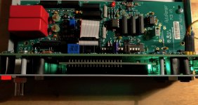
Just soldered the sockets in and realized that there are both 14pin and 16pin types, so actually four different PNs are required to socket everything:
110-43-328-41-001000, qty1
110-43-308-41-001000, qty2
110-43-314-41-001000, qty1
110-43-316-41-001000, qty1
Now to power up....
BK
I am sorry, I did not include that in the BoM because those things are in my stock and I didn't really think about it. But I should have, of course.
Jan
Jan
No worries, Jan. They are optional after all.
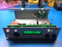
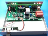
So another one lives. Really superb fitment with the case, etc. Will add some little silicone feet to keep it from sliding around. Feels like a gem of an instrument and has the looks to match. Nice work!
BK
So another one lives. Really superb fitment with the case, etc. Will add some little silicone feet to keep it from sliding around. Feels like a gem of an instrument and has the looks to match. Nice work!
BK
Attachments
Well done! BTW I have a few more complete kits left for any new-comers. PM me if interested.
Jan
Jan
A tip and a wish
My unit is up and running and seems to function well. 🙂
Great work Jan!
The tip:
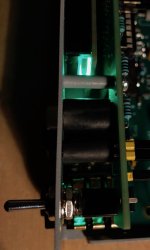
Add heat shrinks to the buttons and the LEDs to mitigate false light from the display and LEDs to hit non-actuated buttons. The buttons are quite transparent.
The wish:
The instructions for the calibration procedure in the spreadsheet can be more clear than they actually are. Or I might be a dumb-*ss (my ex-wife will tell you so if you speak to her).
E.g. Display Accuracy, step 1a:
Where are other areas in the calibration procedure where the instructions can be made more clear and specific.
A short video will tell more than 1000 words. 🙂
My unit is up and running and seems to function well. 🙂
Great work Jan!
The tip:
Add heat shrinks to the buttons and the LEDs to mitigate false light from the display and LEDs to hit non-actuated buttons. The buttons are quite transparent.
The wish:
The instructions for the calibration procedure in the spreadsheet can be more clear than they actually are. Or I might be a dumb-*ss (my ex-wife will tell you so if you speak to her).
E.g. Display Accuracy, step 1a:
Its unclear what is measured and for what purpose. 😕Insert 1kHz 1V signal at SE input as measured on DMM at TP7, as accurate as possible
Where are other areas in the calibration procedure where the instructions can be made more clear and specific.
A short video will tell more than 1000 words. 🙂
Attachments
+1 on an assembly/ calibration video.
Will avoid all kinds of confusion from lack of experience, or that comes with the territory of written instructions / ESL
I’ve always had the hunch that if kit producers regularly did this it’d add years to their lifespans.
Likelihood is high a big chunk of their customer base are visual learners / painting by numbers in the beginning.
Hi Kim,
Yes the non-activated buttons still transmit some light from other buttons. I don't think there would be confusion as the light level is much lower than the activated ones, but your solution with heat shrink tubing sounds good.
I am a little puzzled with your comment on the cal procedure. Maybe I am blinded because I wrote it. But the line you quoted:
' Insert 1kHz 1V signal at SE input as measured on DMM at TP7, as accurate as possible' do you mean the 'as accurate as possible' part?
Maybe I should say: 'Insert 1kHz signal at SE input. Adjust the level to 1V RMS, as accurate as possible, as measured on DMM at TP7'.
Is that more clear?
Jan
Last edited:
Looks like Jan has made progress with the AR to take it to AR Mk II:
The L|A Autoranger | Linear Audio NL
Nice ... I like the "through hole" component philosophy. Fumble-thumbs here doesn't need more SMD in my life than I need. Through hole also for user selection of go-goody parts if that's your thing, so that's also a plus.
I've asked Jan to put my name down on the wait list, so do the same if you're keen.
Note that he's asking for feedback:
I haven't got a Silent Switcher board handy, so I'd opt for include. If I was putting an order in, I think I'd prefer to get an extra for that future job that I haven't worked out what it will be yet.
Maybe the best idea would be:
Not sure whether Jan is up for that. He may just want a simple life.
The L|A Autoranger | Linear Audio NL
What has been deleted is the need for accuracy- and level-calibration. That was a bit of a nuisance as you needed some pretty accurate equipment for that. The new AR MKII is calibrated out of the box and the only adjustment needed is the common mode rejection which can be done using a simple multimeter.
Another piece of good news is that I decided to go away from a pre-assembled SMD board to a bare board with 99% through hole components. This lowers the cost of the kit. Of course, you still need to get the parts you don't have, but it should still be lower cost overall.
At this point, end of June 2019, I am awaiting delivery of boards and the enclosure. I will then build up one final prototype and then notify those on the waiting list.
Nice ... I like the "through hole" component philosophy. Fumble-thumbs here doesn't need more SMD in my life than I need. Through hole also for user selection of go-goody parts if that's your thing, so that's also a plus.
I've asked Jan to put my name down on the wait list, so do the same if you're keen.
Note that he's asking for feedback:
I'm not sure yet whether the SS should be part of the kit or not. Your opinion would help me decide.
I haven't got a Silent Switcher board handy, so I'd opt for include. If I was putting an order in, I think I'd prefer to get an extra for that future job that I haven't worked out what it will be yet.
Maybe the best idea would be:
- AR - SS excluded
- AR + SS included
- AR + SS included + N (where 'N' is the number of extra SS boards)
Not sure whether Jan is up for that. He may just want a simple life.
Yes a simple life would be nice. But boring ;-)
I just send out a mail to everybody who let me know they would be interested in an autoranger. I have a bunch of sets available now, ready to ship the 29th when I have dropped them in Germany.
I have redesigned the attenuation and switching board. Distortion and noise have been lowered a bit, and the manual use is more intuitive. There are some small changes in the attenuation and gain steps, which now range from -42dB to +18dB in 6dB steps. The choice of nominal output levels going to your soundcard remains either 1V or 0.4V. Both single ended and balanced inputs as well as simultaneous single ended and balanced outputs have been maintained. Some of the improvements are the result of lowering the input impedance from 100k to 15k. Every piece of audio equipment I know can easily drive 15k. The control and display board as well as the enclosure are unchanged from the original unit. Power is provided, as it was before, by a SilentSwitcher mounted on the back of the enclosure.
The complex calibration process of the first model is no longer needed, only a simple nulling of the common mode output.
The new kit contains a painted and lettered steel enclosure, an attenuator board, a control/display board, a new programmed controller chip and a SilentSwitcher. M3 hardware that fits the threaded studs in the enclosure is also included, as well as a 2*14 pin IC socket holding the controller chip.
Almost all parts are through-hole except for a few SMD ceramic caps large enough to solder with normal gear. So you getting the parts and doing the assembly saves a lot of money; this is diy, after all..
There is some more info as well as the assembly-, user-guide and BOM here.
Jan
Last edited:
Yes a simple life would be nice. But boring ;-)
I just send out a mail to everybody who let me know they would be interested in an autoranger. I have a bunch of sets available now, ready to ship the 29th when I have dropped them in Germany.
Fantastic news.
Order placed. Check your email for the paypal transaction.
😉
Thanks!
BTW a correction: the input resistance is 10k +/- 100 ohms, any attenuation setting. I mentioned 15k somewhere, sorry for that, a leftover from a prototype that didn't survive ;-).
Jan
BTW a correction: the input resistance is 10k +/- 100 ohms, any attenuation setting. I mentioned 15k somewhere, sorry for that, a leftover from a prototype that didn't survive ;-).
Jan
Thanks!
BTW a correction: the input resistance is 10k +/- 100 ohms, any attenuation setting. I mentioned 15k somewhere, sorry for that, a leftover from a prototype that didn't survive ;-).
Jan
Jan, your joking. I want a refund ... kidding.
Thanks for the transparency.
Yes a simple life would be nice. But boring ;-)
I just send out a mail to everybody who let me know they would be interested in an autoranger. I have a bunch of sets available now, ready to ship the 29th when I have dropped them in Germany.
I have redesigned the attenuation and switching board. Distortion and noise have been lowered a bit, and the manual use is more intuitive. There are some small changes in the attenuation and gain steps, which now range from -42dB to +18dB in 6dB steps. The choice of nominal output levels going to your soundcard remains either 1V or 0.4V. Both single ended and balanced inputs as well as simultaneous single ended and balanced outputs have been maintained. Some of the improvements are the result of lowering the input impedance from 100k to 15k. Every piece of audio equipment I know can easily drive 15k. The control and display board as well as the enclosure are unchanged from the original unit. Power is provided, as it was before, by a SilentSwitcher mounted on the back of the enclosure.
The complex calibration process of the first model is no longer needed, only a simple nulling of the common mode output.
The new kit contains a painted and lettered steel enclosure, an attenuator board, a control/display board, a new programmed controller chip and a SilentSwitcher. M3 hardware that fits the threaded studs in the enclosure is also included, as well as a 2*14 pin IC socket holding the controller chip.
Almost all parts are through-hole except for a few SMD ceramic caps large enough to solder with normal gear. So you getting the parts and doing the assembly saves a lot of money; this is diy, after all..
There is some more info as well as the assembly-, user-guide and BOM here.
Jan
Hi Jan,
This is great news that you have come out with a new version of the Autoranger!
Reducing the input impedance to get some improvement in performance seems like a good move, but I do wonder if there may be some tube-based preamps and the like that might be affected a little bit by a 10k load. What do you think?
For such applications, of course, a simple unity-gain IC buffer could easily be added by those needing it (although some tube preamps can put out more than 15V peak).
Cheers,
Bob
Hi Bob,
I looked a quite a lot of stuff I could find online. Many have cathode-followers these days to be able to drive long cables and low-Zin (solid state) power amps. Including serious diy designs.
But in a pinch one could add an input series R for a higher defined Rin because the AR Rin is quite constant at each setting: 9.948k to 10.04k calculated.
Jan
I updated the Bill of Materials, some errors in numbers, and the LEDs I listed are out of stock at Mouser so I listed a different type.
The LEDs for the control board are totally uncritical as long as they are 3mm diameter to fit the front panel.
Jan
The LEDs for the control board are totally uncritical as long as they are 3mm diameter to fit the front panel.
Jan
- Home
- Design & Build
- Equipment & Tools
- Autoranger for soundcards