A few iterations later:
I tapped thread into the lazy Susan, so both the top and bottom can be taken of separately.

3D printed spacers, strong enough for now.

Adjustable feet:

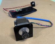
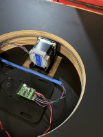
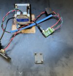
Small 3D printed connection box. Amplifier laptop-style power supply is also powering the stepper.

Audio interface and amplifier:

I tapped thread into the lazy Susan, so both the top and bottom can be taken of separately.
3D printed spacers, strong enough for now.
Adjustable feet:
Small 3D printed connection box. Amplifier laptop-style power supply is also powering the stepper.
Audio interface and amplifier:

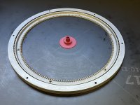
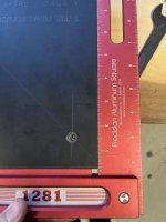
I haven't given up on my build. I got a new circle jig to use, took most of my available time to get it up and running but I was able sink the bearing into the top plate before I ran out of time. One good thing leaving the cut up plywood pieces under heavy weights for a long time made them pretty flat again.
I took apart the test jig the base will might still be useful, new gear attached and stepper motor mounted to frame.
I took apart the test jig the base will might still be useful, new gear attached and stepper motor mounted to frame.
Attachments
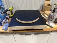
More progress. All the internal circle cuts are made now and a small pocket routed out to get the gear to the right height to meet up with the slewing ring. I need to cut a channel for the power and USB cables, fix all the layers together and cut the outside circle of the top pieces.
Attachments
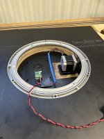
I'm re-using this rotation table for my 3D scanner. If you want to do that also, keep in mind that you need a way to feed cables to steppers, microphone and speaker and you need a stationary stand for the speaker.
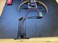
Of course there are multiple solutions (Klippel uses a cable guide that wraps around for the cables), but here is mine:


Several cables are fed through the hole. Some attach to the stationary speaker; some move around with the measurement arm.
The speakers rests on the stationary part of the rotation table. If I want to measure a rotating speaker with a stationary mic (without sound field separation), I can simply put the speaker on the rotating (wooden) top of the rotation table.
Of course there are multiple solutions (Klippel uses a cable guide that wraps around for the cables), but here is mine:
Several cables are fed through the hole. Some attach to the stationary speaker; some move around with the measurement arm.
The speakers rests on the stationary part of the rotation table. If I want to measure a rotating speaker with a stationary mic (without sound field separation), I can simply put the speaker on the rotating (wooden) top of the rotation table.
I'm not sure if I will use it for that purpose but everything will be demountable and easily adjusted if I do. Hopefully you get the scanner sorted out by the time I have the basic table built 🙂
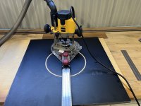
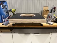
More progress, I got a rail square attachment that I tried out to trim up the base section and make it square. It works well and is good for quick square cuts. I finally found the reason why I bought the 75mm track saw 🙂
It is now a pretty solid base. A few more little operations and it should be ready to test.
It is now a pretty solid base. A few more little operations and it should be ready to test.
Attachments

Well done Duncan, I've added a lead sheet on the Bottom to increase stability on mine
Weight can be added easily if you get one of those cast iron weights either from a retailer or a second hand source. a great idea by the way!
I got this
https://www.decathlon.fr/p/plaque-p...ndeen-45x45-cm-8-mm/_/R-p-X8292359?mc=8292359
at a lower price of course but you get the idea
https://www.decathlon.fr/p/plaque-p...ndeen-45x45-cm-8-mm/_/R-p-X8292359?mc=8292359
at a lower price of course but you get the idea
In truth, cutting a perfect square panel and machining a circle in the center is more difficult than it seems. One would think it is a simple construction, but it has to be nearly perfect or our eyes will notice.
I ended up using 4 pieces of 17mm formply for the base that is approximately 60cm x 60cm in size. It is relatively heavy, I don't know that I want to make it much heavier. The top rotating pieces are in contact with the base to aid in stability and strength, they will slide on some grease. It remains to be seen if this is a good idea or not but the stepper motor is quite strong and the gearing is relatively high for torque.Well done Duncan, I've added a lead sheet on the Bottom to increase stability on mine
I can always build the outrigger platform that I showed in the first post if more stability is needed for heavy speakers.
Do your eyes notice something?One would think it is a simple construction, but it has to be nearly perfect or our eyes will notice.
No not at all... I am just recalling all the times I tried to cut a square panel and had to do it twice.
Duncan,
it still not clear to me why you did a routing in the upper plate and the base for the bearing and putting grease in between the plate ?
it still not clear to me why you did a routing in the upper plate and the base for the bearing and putting grease in between the plate ?
To make a cross between using two sheets of melamine with a central pin and grease and using a bearing for the motion. By having the platform be in contact with the base the load is spread. There is a bit of mechanical slop in the bearing, the idea is to see if this avoids it. If it doesn't work all I have to do is cut a spacer to fit under the bearing and it won't be flush anymore.
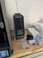
I felt that the old filament dryer I had was not a good visual match for the K1Max so I got the matching one from Creality, so far I like it.
I designed some new parts to mount the Tic board and a back panel for the USB and DC power inlet, printed in ABS-GF. I had to design the mounting lines of the bolts so they were not exactly the same due to the size of the parts and only having 17mm of ply depth to fit them in. Next step is testing it out 🙂
I designed some new parts to mount the Tic board and a back panel for the USB and DC power inlet, printed in ABS-GF. I had to design the mounting lines of the bolts so they were not exactly the same due to the size of the parts and only having 17mm of ply depth to fit them in. Next step is testing it out 🙂
Attachments

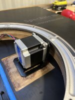
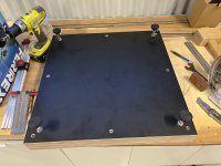
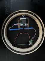
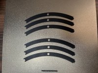
I have had to abandon the idea of having the platform in conntact with the base. It did do both of the things that I wanted which was to damp the movement of the turntable and take out the mechanical slop of the pinion and gear mating. Unfortunately there is too much variation in the casting of the slewing ring and the flatness of the plywood I used. I also noticed that the ball bearings had gone rusty in the slewing ring even when it was kept in a cupboard. I took it apart again cleaned it all up and used some thicker lithium grease this time. I made some spacers on the printer, the one for the top I could just fit on the bed in one piece, the lower one I had to split up. I used modelled up some dovetail connections so I could print them in sections and fit them back together.
It works and I can move it backwards and forwards to the expected positions. So far the mechanical noise of the moving bearing is horrible. It sounds like a Ducati engine at idle, for anyone not familiar, a clattering mess. I have found a few videos of other similar turntables with the same sort of gear and they all sound similar. Maybe I should have gone with the belt 🙂
It works and I can move it backwards and forwards to the expected positions. So far the mechanical noise of the moving bearing is horrible. It sounds like a Ducati engine at idle, for anyone not familiar, a clattering mess. I have found a few videos of other similar turntables with the same sort of gear and they all sound similar. Maybe I should have gone with the belt 🙂
Attachments

- Home
- Loudspeakers
- Multi-Way
- Automatic Polar Measurements using ARTA, stepper motor and Tic Controller