To clarify, When I asked about the high-side optocoupler 'swinging', I was asking if its output was swinging from the pin 5 voltage to the pin 8 voltage.
To check this, you'll need to use your scope in differential mode if all you have is a mains powered scope.
To check this, you'll need to use your scope in differential mode if all you have is a mains powered scope.
Can you be more specific about what you mean with 'swinging'?
Do you mean there should be a point which has optocoupler Pin5 voltage and then it jumps/swings to Pin8 voltage?
I have a pretty good digital scope, but the differential measurement calculations are not the fastest on the scope unfortunately. There is some delay
Is there an other way to check?
Do you mean there should be a point which has optocoupler Pin5 voltage and then it jumps/swings to Pin8 voltage?
I have a pretty good digital scope, but the differential measurement calculations are not the fastest on the scope unfortunately. There is some delay
Is there an other way to check?
There are no calculations in differential mode. The scope would be used in analog mode. The scope should be able to measure anything in differential mode that it can in single channel mode.
It's difficult to measure this with the output transistors in the circuit. If I'm not mistaken, we've already confirmed that the signals were OK with the output FETs out of the circuit.
It's difficult to measure this with the output transistors in the circuit. If I'm not mistaken, we've already confirmed that the signals were OK with the output FETs out of the circuit.
Maybe I do something wrong with digital scope with the differential measurement. Multiple forums described that differential mode with a digital scope is simply doing the math CH1 - CH2. No channel inverting and ground leads connection needed.
Do you agree with this?
Do you agree with this?
Does your scope have an invert button for channel 2?
Do you know how to get it to operate in pure analog mode?
Do you know how to get it to operate in pure analog mode?
There is not a specific invert button.
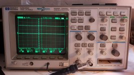
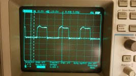
On the photo 1 you see the result of pressing button A1 or A2 (Ch1 and Ch2).
Pressing on that button makes it possible to change the coupling, inverting etc.
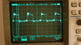
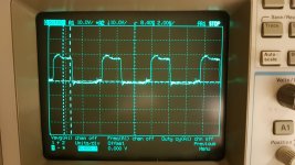
On photo 2 you see pressing the button +-
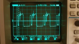
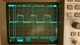
On Photo 3 you see clicking on function menu 1
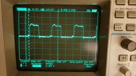
On photo 4 you see clicking on function menu 2
I have not yet found the possebility to use this scope in only analog mode.
On the photo 1 you see the result of pressing button A1 or A2 (Ch1 and Ch2).
Pressing on that button makes it possible to change the coupling, inverting etc.
On photo 2 you see pressing the button +-
On Photo 3 you see clicking on function menu 1
On photo 4 you see clicking on function menu 2
I have not yet found the possebility to use this scope in only analog mode.
Attachments


Last edited:
For image 1, switch to ch2, DC coupling, inverted, 5v/div and probe on the 12v PS positive terminal.
Took some time, but I found how to measure differential.
What excactly would you like me to measure?
I found out some more information. When starting up with a floating power supply on high-side HCPL3180 Pin5 and Pin8 it works perfectly, also after disconnecting the floating power supply while operating it works perfectly.
It seems like it only has problems when starting up without a floating 15v supply.
Last edited:
Without the 15v supply, what does the signal look like across pins 5 and 6 of the high-side optocoupler?
With or without output fets?
With output fets installed and without 15v supply it has a very high current draw on the high side output fets and a hard to trigger signal. Hard to measure precisely.
With output fets installed and without 15v supply it has a very high current draw on the high side output fets and a hard to trigger signal. Hard to measure precisely.
Without the extra supply.
Set everything up and power up just long enough to get a photo of the waveform before anything overheats.
Set everything up and power up just long enough to get a photo of the waveform before anything overheats.
The two channels need to be on the same vertical amp setting. 10v/div should be enough to prevent the waveform from going off of the display.

Make the same readings on the bases of the drivers and on the emitters of the drivers. Place ch2's probe on the source leg of the high-side FETs for both tests.
Those look OK.
With the ch2 probe on the FET source again. post the waveform on the gate leg of the high-side FET. Confirm that both are the same.
With the ch2 probe on the FET source again. post the waveform on the gate leg of the high-side FET. Confirm that both are the same.
- Home
- General Interest
- Car Audio
- Audison SR1Dk output driver card, no High-side output