

Those look OK as well. Does it possibly oscillate at a different frequency when using the 15v supply?
What's the difference in the drive signals at the output gates when using the external supply and it's not used?
I'd expect the only difference to be amplitude for the high-side FETs.
I'd expect the only difference to be amplitude for the high-side FETs.
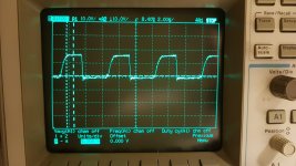
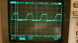
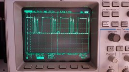
I also notice that during the startup without supply, the signal is very distorted. The clean photo's from previous posts are not constantly this clean.
All photo's taken are from single screenshot made with the oscilloscope. In real life the waves are very glitchy.
They also look like this, I took different screen samples from the same measurement: (output fet referenced to secondary GND)
Swaping this driver board for an other SR1Dk driver board makes the amplifier to work perfectly.
Attachments


Last edited:
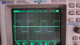
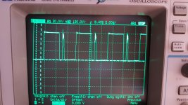
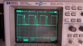
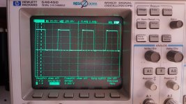
Took some differential measurements between the High-side fets Source and Drain.
Different single shot photo's from the same measurement.
There are ON spikes during the periods the fets should be OFF. I'm not sure if this is a unstable signal glitch or a real signal. I know this scope can take a LOT of samples in each single screen shot, so I don't think it's a scope glitch. Maybe this could be the reason of the extra current draw. The signal is unstable
Attachments
Last edited:
Correct, with supply there are no ON pulses.
The random pulses seems to be present 90% of the single screenshots.
The random pulses seems to be present 90% of the single screenshots.
A button on the scope next to run/stop.
It takes close to a million samples and "pauses" the screen. A snapshot in other words
It takes close to a million samples and "pauses" the screen. A snapshot in other words
I swapped the used output fets for brand new ones (IRFP264N standard, new ones are IRFP4332). Amplifiers protect light goes on now sometimes during startup without floating supply on HCPL3180.
(Switches happily with floating 15v supply, or with an other SR1Dk driver board installed).
Tried to filter the HCPL3180 Pin5 and Pin8 with a little cap across, to see if that works. No positive result.
(Switches happily with floating 15v supply, or with an other SR1Dk driver board installed).
Tried to filter the HCPL3180 Pin5 and Pin8 with a little cap across, to see if that works. No positive result.
Are these driver boards identical in every way?
I was told a few yeas ago that there was a modification to the boards and the authorized repair shops weren't even trying to repair the old boards. They simply replaced them.
I was told a few yeas ago that there was a modification to the boards and the authorized repair shops weren't even trying to repair the old boards. They simply replaced them.
I have 2 identical boards and one (I think??) newer version.
The board which I currently is one of the identical boards.
The good reference board is an other version, but I have an identical board laying around from the same version. This board works properly too, but that amp has been build up again, so I need to take that apart.
The current board is shown in post #1
Last edited:
Well, I have to say that I'm confused by your scope images. The spikes I see, in no way, correspond to the drive signals. There is a tiny glitch on the edges of the drive signals but they aren't likely to cause the spikes so far from where they are.
The output fet drive signals are glitchy as well. The same unstable glitch signal is present at the gates of the output fets.
The LM319 Pin12 (goes to the input pin of the driver board, is a clean signal).
Should I try to replace the LM219 on the driver board once again?
That is the component which 'seperates' and phase shifts the square wave 180 degrees and forwards the signal to the optocouplers.
Since there are ON-spikes during the square wave OFF periodes.
Last edited:
The differential signals with the scope free-running never show the spikes. The spikes should show up if the current draw is constant.
At this point, I don't really have any suggestions. Have you tried measuring the resistance across every component (reversing probes to check both ways) to see if there was a difference between the boards?
At this point, I don't really have any suggestions. Have you tried measuring the resistance across every component (reversing probes to check both ways) to see if there was a difference between the boards?
Yes, every reading was as good as the same, except between the Hi-side HCPL3180 Pin5 and Pin8.
The bad driver board had a much lower resistance.
So, I took out the High-side optocoupler and re-measured between the Pin5 and Pin8 vias from the board, as well as the seperate optocoupler pins. Both rode a very high resistance as the other good driver board....
So strange.
I re-installed the optocoupler and re-measured. A very high resistance again (good value). Powered on the board, re-measured, a much lower resistance again.
I don't get it
- Home
- General Interest
- Car Audio
- Audison SR1Dk output driver card, no High-side output