I was also surprised to hear them with a full sound and a better volume.
But now I have to try to remove the entire board with power supplies. Those very thin wires worry me. If I remove it I can see every resistor and capacitor to buy.
But now I have to try to remove the entire board with power supplies. Those very thin wires worry me. If I remove it I can see every resistor and capacitor to buy.
I would not replace anything and leave it as it is. The signal path only has two power resistors and a mkt capacitor. These live forever, there are no electrolytic caps or other components that can degrade on this pcb. And when both speakers play equally loud, you can be pretty sure the high voltage supplies are fine too. If it works, don't fix it. Unsoldering the transformers is always a risk.
ok, tomorrow I'll also check the capacitor area and in addition to being dark yellow, they are two large ones and I could be wrong, but I seem to remember seeing them as electrolytic. I'll check again to see if I was wrong!
Could be there is indeed an electrolytic, on my ancient ES200 there is not but the models evolved constantly and your ES300 is probably of later age.
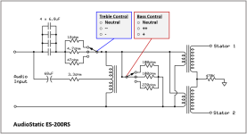
In later models Audiostatic added an electrolytic cap in series with the low frequency feed to the mirror drive transformer as well as some resistors (switchable in the RS models) allowing a few dB adjustement for high/low balance. They also changed the value of the large 47uF MKT and switched from one large one to 4 smaller ones, my guess is that was cheaper and better available.
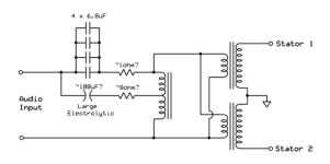
Here is a schematic of a later ES200RS model, the later 300RS is identical afaik. I also include a schematic of an older one of an ES300, don't know what version.
If it is only one cap to replace, you can change that without taking off the whole PCB. It's fiddly but dodable, use a small mirror. It's even possible to change all diodes and caps on the HV supply that way but it's a time consuming way to do it.


I think that, if I saw correctly yesterday, but later I'll go back to the warehouse and check again that the big 100uF, on mine, are two, maybe 50uF each. I think I can remove the whole block without doing any damage - one of the two already has the whole block moving, I think a couple of levers will come out. Thanks for the diagrams. top!
after removing the board the worst that could happen came out - obvious signs of previous interventions, one of the three transformers is not connected, the board has been interrupted as you can see on two tracks and some component has been removed - perhaps a burnt resistor. in fact the lowest transformer and which you can see is also a little different from the other two is most likely shorted. on both boards the tracks have been scratched/interrupted and only two transformers are connected and working.


Yes, they disconnected the mirror drive transformer which is the bottom one.
The mirror drive transformer is just an autotransformer with a single winding with a tap. Could be they had a DC issue on their amp, that would explain the burned resistor. Chances are good the transformer itself is fine, not easy to kill those. Check it visually for signs of overheating.
If it looks ok, I suggest restoring the PCB to it's original design, put in a new resistor and see what happens. Use low volume and preferable an amplifier that has overcurrent protection for testing.
visually it does not present strange signs, it still has 4 wires like the other two and with the multimeter it gives a hint of a signal that then immediately goes to zero. why disconnect it and eliminate the burnt resistance and also interrupt the two tracks? which then is not clear why it only has two 33uF 100V capacitors. it seems like a completely different board, with different resistance values - the white one you see is 4ohm, while on the other board there is a green one of 3.3ohm. all very strange!
Not really strange, Audiostatic changed a lot over the years. Is the other pcb identical?
The mirror drive transformer has only three connections that are used, there should be continuity between all three with only a very low resistance. Don't know the values but it will be a few ohms at max, probably even less.
The mirror drive transformer has only three connections that are used, there should be continuity between all three with only a very low resistance. Don't know the values but it will be a few ohms at max, probably even less.
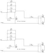
Made a quick schematic from the photo, so you can see what was done. Ignore the second winding on the mirror drive transformer, I did not have the correct symbol in the library. The 5.6 ohm is not a verified value, check that with the other channel if that is still readable.
Upper picture is as it should be lower after the two tracks are broken. That way you loose the mirror drive functionality. The mirror drive provides a 6dB/oct boost under approx. 300Hz, that compensates the dipole roll-off. Without it you will have to little low frrequency output.

Upper picture is as it should be lower after the two tracks are broken. That way you loose the mirror drive functionality. The mirror drive provides a 6dB/oct boost under approx. 300Hz, that compensates the dipole roll-off. Without it you will have to little low frrequency output.

the wires coming out of the plastic are a mess - they practically break, but I can recover them by extending them from the central pin. on the board the third one also had 4 poles to solder. they were then detached but to me it seems to have 4 wires. I'll check better later, obviously! yes, the two boards are identical.
so, in addition to the burnt resistor, two 6.8uF capacitors were also removed !😕
transf, pic:

so, in addition to the burnt resistor, two 6.8uF capacitors were also removed !😕
transf, pic:
No, they are still there. The big red blocks. Those are mkt types.so, in addition to the burnt resistor, two 6.8uF capacitors were also removed !
Compare both pcb's to check for differences and missing parts.
Make sure the left top transformer still measures good after the pin broke. The wire on the secundary winding is extremely thin and fragile. Be carefull not to break it.
Do you use a solder sucker to remove all the solder from the joints? You should.
you're right, I didn't use a vacuum cleaner but I take it because it needs to be cleaned well. yes, I checked the values of the two above again and they are ok. then for the third one at the bottom, it does have 4 wires but the one on the bottom right is perhaps only in the hole of the board but does not connect to the copper track - logo area
assuming the third transformer is ok,
I'm going to restore the original connections like this - like a pic.
I still have a doubt regarding the 4 points to solder. 1 / 2 / 4 you can clearly see that they go on the board tracks, but is 4 just for fixing / fixing the board?

I'm going to restore the original connections like this - like a pic.
I still have a doubt regarding the 4 points to solder. 1 / 2 / 4 you can clearly see that they go on the board tracks, but is 4 just for fixing / fixing the board?
4 is used, it's the ground connection for the transformer. Terminal 3 is unused. When you look at the bottom side of the transformer my guess is that there is no wire connected to that pin. 1 is the center tap, 2 is the top side of the transformer.
I still wonder how they managed to burn out the resistor. I've never ever seen that on an Audiostatic. It's either DC from a faulty amplifier, or they drove the speaker with such extreme high levels of low frequency signals that the mirrordrive transformer went into saturation. When it saturates it basically turns into a short, placing full amplifier power over the resistor.
When you look at the schematics of the 200RS and the later 300 I posted above, note that Audiostatic added a large 68 uF capacitor in series with the burned out resistor later on. That blocks DC and probably also forms some LC filtering circuit with the transformer to create some peak in the response to improve low frequency response even more.
You might consider upgrading yours to the same circuit. The way it is now does not make a lot of sense to me because of the large capacitance of the 4 caps combined (almost 90uF). I doubt this is original. Can you find a date code on the Visaton capacitors?
As you can see in the schematics, usual is 68uF in series with the center tap and around 27 (4x 6.8)uF to the top of the mirror drive.
How does the other channel look?
I'll update you later. I also see very strange things in that board. It seems that after burning a resistor we fixed the other one accordingly. Crazy! I want to check the third transformer well as you told me and hope that it has values and is not interrupted / broken.
The mirror drive transformer is wound from very thick wire, not easy to burn that out. The resistor in series with it will go first. But it never hurts to check the transformer for continuity.
No worries, this is all easily fixable.
No worries, this is all easily fixable.
yes, the copper winding of the 3 is definitely a thicker wire. yesterday talking to the former owner he said that the sockets/purchased used, with two faults/problems at two different times. he doesn't remember exactly what, but they replaced the mylar panel - that's what they told him, but at this point given the situation, I think they told him a lot of ********/lies.
- Home
- Loudspeakers
- Planars & Exotics
- Audiostatic ES300