if I see correctly, your frame has rounded edges where the mylar adheres well when air is sucked in and remains taut.
I ask - is it better to take the measurements by removing the black acoustic sheet?
I ask - is it better to take the measurements by removing the black acoustic sheet?
Yes, edges and corners are all rounded. The black stuff around the opening in the stretcher is neoprene foam that allows the diaphragm to be pressed into intimate contact with the sometimes concave frame of the driver grid.
I am not familiar with the construction of the ES300, so I don't know what the acoustic sheet is, but if you're measuring diaphragm resonance using the technique I used, you'll want just the diaphragm (with or without whatever conductive coating is on it).
I am not familiar with the construction of the ES300, so I don't know what the acoustic sheet is, but if you're measuring diaphragm resonance using the technique I used, you'll want just the diaphragm (with or without whatever conductive coating is on it).
If you're referring to the neoprene on my stretcher, not using the neoprene might give a final resonance on the driver that more closely matches the resonance on the stretcher, but as it is, there's a known 9 Hz offset that works reliably. If I want 86 Hz resonance in the driver to match the factory resonance, I set resonance on the stretcher to 77 Hz.if I see correctly, your frame has rounded edges where the mylar adheres well when air is sucked in and remains taut.
I ask - is it better to take the measurements by removing the black acoustic sheet?
I'll load them onto the van by this evening, then I'll remove the black acoustic canvas and take some initial photographs. Then I'll do a low-volume test and take a closer look to see how it's assembled.
as I was saying... maybe they are the first models and the frame is made of raw wood with black canvas covering it. three power supplies embedded, it is not clear how and some resistors in series outside the power supply area, placed in the lower area of the frame where there is the mylar.
completely oxidized:


completely oxidized:
also on one there are the aluminum strips that hold the copper/wire loop, in the lower part that have detached from the milar frame - 3 completely and 2 others only on one side. this however does not seem to have any effect on the sound which remains very, very low.
Oh now I see where the black stuff is. I remember a similar one offered second hand. This is a very old one!
These are indeed very early ones, I think these models were still sold under the Megalith name, late 1980's. I own a pair of very early ES200's of identical construction, see https://www.diyaudio.com/community/threads/anyone-knows-this-unknown-audiostatic-es200-model.408281/. Interface looks identical too, with the mirror drive transformer.
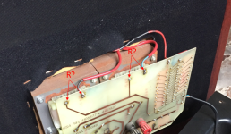
Looks like they were not always stored in a dry location. But nothing terrible. Do you have a multimeter? If not, you should get one. Try measuring the resistance between the points indicated in the picture. And measure the resistance of the four 47k resistors that are connected to on each stator, they look a bit crusty.
It all looks factory built to me, no signs of a later rebuild. So my bet is still on the coating. They must be at least 35 years old by now. You'll need to take of the cloth completely first and desolder the wires to the ESL element. The element is glued to the MDF frame in these, it easily pushed out breaking the glue bond. White or black stator wires?

yes, they are old and yes, they have taken humidity, you can see it. I will proceed with the measurement of the resistance on the 4 points indicated.
I also have to figure out how the three transformers are locked into the box - maybe glued, it's not clear.
I also have to figure out how the three transformers are locked into the box - maybe glued, it's not clear.
🙂Oh now I see where the black stuff is. I remember a similar one offered second hand. This is a very old one!
I know this person who had them well and they took them used many years ago and are in excellent working condition.
Do not try to take the transformers out! They are glued in the wooden frame. It takes a lot of force to remove them, with a high risk of damaging them. So leave them there.
There is no need to take them out at this point anyway. If you later need to remove the pcb (to rebuild the HV supply for instance), unsolder the connections of all three transfomers. That allows you to remove the pcb leaving the transformers in place.
There is no need to take them out at this point anyway. If you later need to remove the pcb (to rebuild the HV supply for instance), unsolder the connections of all three transfomers. That allows you to remove the pcb leaving the transformers in place.
Btw I aquired my old pair of ES200 about a year and a half ago, they too were still factory original. And they too still played albeit very soft. So the coating Audiostatic used back then must have been quite stable. But after almost 30 years, it's time for a rebuild...
The worst thing of these is separating the wooden panels from the esl element. Originally they are glued. It takes quite some force and there is a risk of splitting the wood. When unlucky some of the metal bars may get loose. I fixed them with super glue.
I have to say that after a good sleep and having seen how they are built - I am more relaxed - I thought they were more complex.
I suspect that the oxidized resistors need to be changed - there are 5 in series + another 5 in series. I also noticed that on the board on the transformer side, there are two dark yellow capacitors and a fairly large resistor. on one side it is green and round, on the other it is square and white... hum???
yes, i saw that by unsoldering the six points of the three transformers you can detach the board and better control everything. so i will not remove the transformers from the chassis. ok
and then...i thought i'd do a check on the whole power supply department - everything under the plastic box - then again a listening test and a microphone measurement.
what do you think?
what do you think?
I am by no means an expert on electrostatic speakers, but very interested in their design. I am sure the people that know are right in that the mylar needs replacing. I have a book by E. Fikier which says that the membrane of the Audiostatic speakers has a very high surface resistance and needs at least 24 hours to charge, and that Audiostatic advises that they are best left powered on continuously even when not in use. Not saying your membrane is good, just that you can only judge them after 24 hrs of charging. Please correct me if I'm wrong.
In my experience they charge much faster, within 15 minutes.
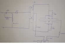
Some usefull information: The interface is very basic on these. Here is the schematic I made of my ancient ES200. The 47uF cap is a very large MKT, the 1R5 is a round green wirewound (10W or so), the 5.6 ohm is a 5W white cemented resistor. Component values may differ a bit on yours because of the larger ESL element. There is really nothing to go wrong here other than the two audio transformers burning out as mentioned before.

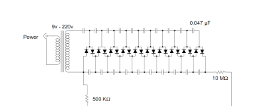
The block with HV supply is a simple voltage multiplier with 20 diodes (probably 1N4007) and 20 caps (47nf). It is used in all Audiostatics, here is a schematic from an ES50 that will be identical.

In your case the mains transformer will be missing and the mains is directly connected to the voltage multiplier. The transformer was only used in markets with a different mains voltage from 220/230V, in which case a small external power adapter was used to provide the 9V AC input. On my ES200, there is is a trim potentiometer on the mains side to adjust the voltage but your's don't seem to have that. I guess my 200's are even older.
The high voltage supply provides the bias to the membrane and it generates approx. 5kV DC so keep your multimeter far away from it. You'll need a special HV probe to measure the output, with an input resistance of 10 gigaohms or more. These are not cheap and not worth buying for one time use. Since both speakers have the same problem, it is unlikely that the HV supply is the fault anyway.
In my experience the HV supply usually still works fine, even after 30 years. With everything fully discharged you can check the diodes with your multimeter. Still it doesn't hurt to replace all diodes and capacitors in the HV supply for piece of mind. I usually increase the capacitors to 68nF, gives a bit more power to compensate for leakage losses.
If you want to measure them with a microphone, they should do around 82dB/1W/1m if I remember correctly.
Some usefull information: The interface is very basic on these. Here is the schematic I made of my ancient ES200. The 47uF cap is a very large MKT, the 1R5 is a round green wirewound (10W or so), the 5.6 ohm is a 5W white cemented resistor. Component values may differ a bit on yours because of the larger ESL element. There is really nothing to go wrong here other than the two audio transformers burning out as mentioned before.

The block with HV supply is a simple voltage multiplier with 20 diodes (probably 1N4007) and 20 caps (47nf). It is used in all Audiostatics, here is a schematic from an ES50 that will be identical.

In your case the mains transformer will be missing and the mains is directly connected to the voltage multiplier. The transformer was only used in markets with a different mains voltage from 220/230V, in which case a small external power adapter was used to provide the 9V AC input. On my ES200, there is is a trim potentiometer on the mains side to adjust the voltage but your's don't seem to have that. I guess my 200's are even older.
The high voltage supply provides the bias to the membrane and it generates approx. 5kV DC so keep your multimeter far away from it. You'll need a special HV probe to measure the output, with an input resistance of 10 gigaohms or more. These are not cheap and not worth buying for one time use. Since both speakers have the same problem, it is unlikely that the HV supply is the fault anyway.
In my experience the HV supply usually still works fine, even after 30 years. With everything fully discharged you can check the diodes with your multimeter. Still it doesn't hurt to replace all diodes and capacitors in the HV supply for piece of mind. I usually increase the capacitors to 68nF, gives a bit more power to compensate for leakage losses.
If you want to measure them with a microphone, they should do around 82dB/1W/1m if I remember correctly.
Last edited:
- Home
- Loudspeakers
- Planars & Exotics
- Audiostatic ES300