Peter,
Thanks for the kit. Received it today and it looks great. Can't wait to get it done and playing.
I have a few left over Black gates and was wondering if it would be a good idea to use two 4.7 uF caps in super-e-caps configuration after U2 and U3 (AN8005). You had 10 uF caps in original schematic but had crossed over the value and changed it to 4.7 uF. Is 4.7 uF better than 10 uF or have you changed the value for some other reason?
I tried Super-E configuration in coupling only, but didn't like it, I'm not sure how it works as bypas.
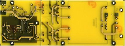
This is a redesigned board layout, accepting only SMD version of CS8412. I changed the value of the bypass caps to provide more open, faster sound. I have a feeling it will work well with new board layout. I also want to keep things simplified, less different cap values to deal with.
Besides that, the power supply traces have been also simplified, there is an option for BG N 1000/50 main filter caps (two of them mount outside the board), bleeder resistor option added after coupling caps (R11/R12, but I don't feel they needed), additional holes for Caddock TF020 in I/V, and improved layout of high voltage traces on transformer's primary (with two holes for proper fuse mounting). I didn't asembled any of the new boards yet, but I hope the layout is OK 😉
C10 mounts on a bottom, attached directly to pins of R6 and C8. R6 is 220R now. As usually, with BG N short lead (NON POLAR print side) is recommended to mount on + side.
Due to falling exchange rate of USD, the DAC kit price has been increased to $230.
Attachments
DAC kit
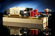
Great looking photo.
What's the current USD price with the Hammond 50W, Cardas dual RCAs and power module?
-Rob
Peter Daniel said:The chassis is not really needed here, I like to mount the DAC on a maple board only (Hammond 50W transformer, Cardas dual RCAs and power module are not included in a kit price but are also available).
Great looking photo.
What's the current USD price with the Hammond 50W, Cardas dual RCAs and power module?
-Rob
Transformer with power module is $30, Cardas dual RCAs $20. The maple board, including bronze standoffs and stainless screws, $20.
WIKIPEDIA Gainclone description...
Anyone seen this?
Wikipedia GAIN CLONE definition
Rightly mentions Peter Daniel, but still could use a re-write.
-Rob
Anyone seen this?
Wikipedia GAIN CLONE definition
Rightly mentions Peter Daniel, but still could use a re-write.
-Rob
Could someone do a brief check on the boards, please. I haven't powered up the DAC yet. Well.. I guess I didn't screw up anything and I can always get new parts if I fry something. 
Instead of using one 4,7 uF cap in the output I used two as super-E-Caps. The solder joint fuse was a great idea but not suitable for 230 V. I soldered the fuse holders sideways. I first tried soldering a fuse straight to the board but the fuse broke when heated. All in all this was a very straight forward job and I didn't have any problems building the board.
These's a few pics in this gallery:
http://www.dvdplaza.fi/galleria/showphoto.php/photo/7973/size/big/cat/500/ppuser/3104
An externally hosted image should be here but it was not working when we last tested it.
An externally hosted image should be here but it was not working when we last tested it.
An externally hosted image should be here but it was not working when we last tested it.
An externally hosted image should be here but it was not working when we last tested it.
 "#¤@£€¤!!! I totally forgot the BNC connector. I don't have any I'll have to wait until monday to get one.
 Maybe an ice cold beer will help

In my dream I was drowning my sorrows
But my sorrows, they learned to swim
The components look like they are installed correctly. Regarding the fuse, although it's rated 125V it should work fine with 230V. I asked Upupa Epops about it and he confirmed.
I tested few different types, but that one seemed to sound the best here.
You can temporary solder RCA input and try it like that.
I tested few different types, but that one seemed to sound the best here.
You can temporary solder RCA input and try it like that.
Thanks Peter for checking my work. Voltage rating was one thing but current rating was another. It was a 2 A fuse which means 460 W power with 230 V (10 times tranformer power rating). I didn't wan't to take any chances with high impedance faults...
I'm working on a dirty and cheap BNC connector. I just can't wait until monday 😀
I'm working on a dirty and cheap BNC connector. I just can't wait until monday 😀
DAC works 
Unfortunately the transformer makes a buzzing sound. I allready tried mains DC filtering but it didn't help.
My BNC connector is not pretty but it works 😀
I used solid core OFC copper wire as center pin and Riken resistor lead as gound pin.
Unfortunately the transformer makes a buzzing sound. I allready tried mains DC filtering but it didn't help.
My BNC connector is not pretty but it works 😀
I used solid core OFC copper wire as center pin and Riken resistor lead as gound pin.
An externally hosted image should be here but it was not working when we last tested it.
Finally had a chance to ABC a Benchmark DAC 1, the internal Dac of a CL-10, and Peter's NOS DAC gold board. While the DAC 1 seems a bit more exact and technical, Peter's board is definitely more musical without losing any detail. The DAC inside the CL-10 is better than I expected, but a touch short of the other two. Peter's DAC is definitely worth the money.
Feeding the X-BOSOZ Preamp from Twisted Pear to a pair of Aleph 2 clones using Brian GT boards and some homemade Focal 3-ways.
Yes, it runs hot with the temp outside being in the 100's, but class A is worth it.
Craig
Feeding the X-BOSOZ Preamp from Twisted Pear to a pair of Aleph 2 clones using Brian GT boards and some homemade Focal 3-ways.
Yes, it runs hot with the temp outside being in the 100's, but class A is worth it.
Craig
DIAR said:Unfortunately the transformer makes a buzzing sound. I allready tried mains DC filtering but it didn't help.
All those transformers buzz, you can control how much by placing the board, or DAC enclosure, on some soft support. The DAC needs approx 2-4 weeks for complete breaking in.
I had Benchmark DAC 1 for a while and preferred NOS. Also, ML360S fell short of the NOS DAC.
Yeah, I could swear I heard resampling errors on the Benchmark, but there was no way to confirm. Just odd clicks and skips. Your NOS has definitely been worth it, even feeding single ended to the X-BOSOZ.
I just pulled my dac out of the enclosure after I started noticing some major changes in the sound, now I understand why people say black gates take a long time to burn in, and Peter, you were certainly right about the improvements. I've noticed the biggest improvement with cymbals. The splashy sound is gone and they have much better defined positioning. It's almost like listening to a really good moving coil setup but with better defined, harder hitting bass.
Is it normal that those N-type Black Gate get warm. They are not hot but clearly warmer than skin temperature.
The transformer got much more silent after placing it on top of one pile of two Vibrapods. Maybe I'll cut the board into two and place the power supply board on soft feet and the DAC board on stiff feet. I've never had any good experiences with soft feet under digital devices.
After a proper burn in I will experiment with different coupling caps. I seem to have Black Gate, Murdorf Supreme, Jensen aluminum and Auricap in stock.
Unfortunately the transformer makes a buzzing sound. I allready tried mains DC filtering but it didn't help.
[/B]
Yes, it does buzz. Certainly at 242v mains I have.
It may buzz more at higher voltage, however, the PS section can be separated from the DAC section (there is a scoring line to make it easier); the four 20R resistors will connect both boards. In that case, PS can be soft mounted, to reduce buzzing, and DAC section can be mounted in a way to achieve best sonics.
Some of the caps run indeed a bit warmer.
Some of the caps run indeed a bit warmer.
- Status
- Not open for further replies.
- Home
- More Vendors...
- Audio Sector
- AudioSector-chip amp kits, dacs, chassis