Peter Daniel said:
When I was using battery power, and having choice of either 2 x 12 or 3 x 12V (per rail) I always opted for the latter.
Peter,
thanks for your response, how do you find the sound changes when you change the power supply from mains to battery?
Is battery powered amp sounds better than mains powered or just different(*), assuming you take care to get the best of both designs?
* my guess is just different(possibly only slight variations) and the amp made eg. chipamp, digital, discretes, tube is much more predominant in determining the character of the sound.
Cheers.
heh peter you should run some test's on this lifepo4 ->http://stores.ebay.ca/PingBattery
way better than sla
way better than sla
I prefer AC power now (with small caps) and would not go back to batteries again:
http://www.diyaudio.com/forums/showthread.php?s=&postid=1105485&highlight=#post1105485
http://www.diyaudio.com/forums/showthread.php?postid=1231532#post1231532
http://www.diyaudio.com/forums/showthread.php?s=&postid=1105485&highlight=#post1105485
http://www.diyaudio.com/forums/showthread.php?postid=1231532#post1231532
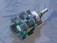
I only use passive stages: either discreet attenuator with quality resistors or TVC.
I was experimenting a bit with active line stages, but in the long run I didn't find them interesting enough and in my best amp it is TX102 that I decided to implement: http://www.diyaudio.com/forums/showthread.php?s=&threadid=76609&highlight=
Important thing is to install the attenuator directly at the amp. If active stage "improves" the sound, it could indicate that the system is not assembled properly.
Some thoughts on a subject can be found here:
http://www.high-endaudio.com/RC-Linestages.html
and here:
http://www.goodsoundclub.com/GetPost.aspx?PostID=957
http://www.goodsoundclub.com/Forums/ShowPost.aspx?postID=257#257
Attachments
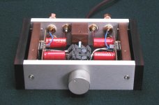
in a proper set-up .......... without pre-amp
Peter -
Gorgeous as usual.
Can you point me to a thread to read regards your statement?
Thanks - Bluto
Power Supply Caps
Hi Everyone,
I ordered the LM3785 Dual Mono Premium Kit a couple weeks ago. I printed out the guide thats on the web page and merrily soldered everything together as per the instructions.
Just a minor warning to those inexperienced people (such as me)
In the guide, it says the premium kit comes with Black Gate N-type caps. This is not true, the web page correctly states that the kit comes with 2X BASIC rectifier components. Being inexperienced, I really don't know what a BG-N type cap would look like compared to a panasonic polar cap (however, I guess the negative signs on the one pole should have been a hint).
The guide is, however, very correct in where it says not to install polar capacitors in backwards as they may explode
Glad I had safety glasses on
Anyway, after the first try, I reversed the caps on the second rectifier board and voila! +35V -35V ..... success!
Boyd
That guide is outdated, and presently contains general info only.
I started a thread with more consistant info with regards to current kits: http://www.diyaudio.com/forums/showthread.php?s=&threadid=123003
I started a thread with more consistant info with regards to current kits: http://www.diyaudio.com/forums/showthread.php?s=&threadid=123003
Peter Daniel said:The optional cap are there to "manipulate" the sound. Originally, those were BG N 4.7/50 and they were supposed to add more warmth and image density to main filter Panasonic caps.
As BG are discontinued now, I supply 10uF Panasonics instead, and they can be used to sort of "improve" the sound of larger caps, as it is commonly practised by other manufacturers. I noticed that in most cases such additional caps only spoil things and it's best to test both setups and choose better sounding option.
The capacitors are polarized and their orientation is critical. Each electrolytic has one pin longer and this should be installed in a pad marked with + on the board. Also, the golden stripe marks the negative side and it installs opposite the +. When those caps are mounted the other way, after connecting power to the amp, they will explode.
Thanks to everyone who made suggestions re. my Gainclone's earthing. Re-did it so it's exactly like the Patek and I have no hum now at all I also decided to dispense with R1 which also helped, especially in terms of a more full bodied presentation.
Peter, I'm having problems sourcing the AN8005's here in the UK for your NOS DAC (thanks for the parts and board by the way!). Is there any reason why I can't use any old 5V regulator?
They have the following stocked in our local branch of Maplins:
The following are made by TSC, and are 150mA ultra low dropout kind:
http://www.maplin.co.uk/module.aspx?ModuleNo=46323&doy=23m5
The next choice are made by National Semi. and are 100mA types - special note they don't need any external components, so I could do away with several Black Gates (C5a/C5b/C8/C9)... :
http://www.maplin.co.uk/module.aspx?ITAG=SPEC&ModuleNo=46470&doy=23m5#spec
Any favourites amongst these two Peter?
Many thanks,
- John
P.S. Is it OK To use 3K resistors for R8 and R9?
I also decided to dispense with R1 which also helped, especially in terms of a more full bodied presentation.Peter, I'm having problems sourcing the AN8005's here in the UK for your NOS DAC (thanks for the parts and board by the way!). Is there any reason why I can't use any old 5V regulator?
They have the following stocked in our local branch of Maplins:
The following are made by TSC, and are 150mA ultra low dropout kind:
http://www.maplin.co.uk/module.aspx?ModuleNo=46323&doy=23m5
The next choice are made by National Semi. and are 100mA types - special note they don't need any external components, so I could do away with several Black Gates (C5a/C5b/C8/C9)...
:http://www.maplin.co.uk/module.aspx?ITAG=SPEC&ModuleNo=46470&doy=23m5#spec
Any favourites amongst these two Peter?
Many thanks,
- John
P.S. Is it OK To use 3K resistors for R8 and R9?
I used AN8005 based on 3rd Kusunoki DAC. I compared those regulators against few other types and they sounded best to me.
Of course you can use different ones, but it's hard to say how they sound. I can always send you some.
3K resistor should be fine. Here's the link how to calculate the values properly: http://www.diyaudio.com/forums/showthread.php?postid=173483#post173483
Of course you can use different ones, but it's hard to say how they sound. I can always send you some.
3K resistor should be fine. Here's the link how to calculate the values properly: http://www.diyaudio.com/forums/showthread.php?postid=173483#post173483
Thanks for your reply Peter.
My budget is maxed out at present so I'll have to go for the el cheapo Maplin option for the time being . When things look up a bit financially I'll order the real McCoys from yourself.
Thanks for that link. I'm going to go with 1K5, and 2 x 2K4 Kiwame's.
I was thinking about the PLL section. You've got 3n3, 330R (used to be 220?) and 0.47uF. The data sheet for the CS8412 recommends 1K resistor, and 0.047uF cap only. Did you try these just out of interest? I have a 270R Caddock left over from another project, so shall use that, but I may try the 1K / 0.047uF combo first.
Cheers,
- John
My budget is maxed out at present so I'll have to go for the el cheapo Maplin option for the time being
. When things look up a bit financially I'll order the real McCoys from yourself.Thanks for that link. I'm going to go with 1K5, and 2 x 2K4 Kiwame's.
I was thinking about the PLL section. You've got 3n3, 330R (used to be 220?) and 0.47uF. The data sheet for the CS8412 recommends 1K resistor, and 0.047uF cap only. Did you try these just out of interest? I have a 270R Caddock left over from another project, so shall use that, but I may try the 1K / 0.047uF combo first.
Cheers,
- John
- Status
- This old topic is closed. If you want to reopen this topic, contact a moderator using the "Report Post" button.
- Home
- More Vendors...
- Audio Sector
- AudioSector-chip amp kits, dacs, chassis