This is actually the only documentation that followed the amp!
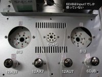
I bought Audioromy's FU-13 SET one year ago. It may be an old version. The tubes are shown in the attached photo by American tube names. 6DJ8 is for input voltage amplifier to accept low level input signal and can be skipped by a switch located on the front panel.
I modified it to reduce global NFB. I changed the value of NFB resistor from 22K to 56K. I like the sonic of low NFB.
Attachments
I replaced the faulty cap for 47uF/160V/105C. Now FU13 works as usual. I believe, that the original cap was from faulty batch. I run the unit more than 3 hours and it was really hot, specially inside. It is american product. Now I will work over the bias to reduce it to ca 65 mA. Then I will try to reduce NFB and see impact on the sound.
Savim
Savim
Bias can be adjusted between 50 and 80mA. The producer advise is 70mA. But here in the Netherlands and Germany a lot of user set the bias to 55mA. We have then lees distortion at high volumes and less heat from the transformers. Sound stays the same.
Savim, good so.
Ronny
Savim, good so.
Ronny
Last edited:
Wow!
what kind of output power do you expect from a push pull?
In any case you wont need to turn up your ovens for the winter.
Happy soldering!
what kind of output power do you expect from a push pull?
In any case you wont need to turn up your ovens for the winter.
Happy soldering!
Hi Koifarm,
Thanks for that.Some posts I have read are a little confusing,talking about readings in volts rather than mA.So I take I just measure across the resistors with my meter set to mA and adjust the pots to the preferred mA rating?
Thanks for that.Some posts I have read are a little confusing,talking about readings in volts rather than mA.So I take I just measure across the resistors with my meter set to mA and adjust the pots to the preferred mA rating?
you read in mv, and calculate w/ ohms law. (I dont know the equation off the top of my head but just google "measure current across resistor").
Or maybe someone who knows this amp and the value of the resistor you are measuring across will chime in.
Or maybe someone who knows this amp and the value of the resistor you are measuring across will chime in.
Thanks wicked.I note some here have changed to using ecc99.I take it this is replacing the ecc88?
The older version pre 2008 or so benefited from changing to ecc99. The newer ones work fine as they are.
Thats ecc82 changed to 99
Thats ecc82 changed to 99
Last edited:
I tried them in place of the 82's and they did not work.Then swapped for the 88's and the amp works fine?? 😕
That's 6n6p that I tried.The 82's are the front outside valves yes? Tried them here and no sound from amp-filaments not lighting either.Swapped them to the the two front centre valves-ecc88,and filaments light and amp works.
That's 6n6p that I tried.The 82's are the front outside valves yes? Tried them here and no sound from amp-filaments not lighting either.Swapped them to the the two front centre valves-ecc88,and filaments light and amp works.
Last edited:
The ECC82s (12au7) are on the outside, yes. Although I do not own that version.
You should be able to read the type on the tubes. Take a look at page 4 where there are presentations of the new version and make sure you dont have one of those.
Also check with another tube, just to make sure you did´nt insert a dead one.
But its best to hope that Koifarm or other experienced user of the old version chime in here.
Hello ali tait and trondareo,
This is what is possible:
Swap ECC82 for JJ ECC99( direct swap ) or 6n6p( after modify filament supply ).
Swap 6dj8( ecc88) for 6n6p ( direct swap ).
Ronny
This is what is possible:
Swap ECC82 for JJ ECC99( direct swap ) or 6n6p( after modify filament supply ).
Swap 6dj8( ecc88) for 6n6p ( direct swap ).
Ronny
Oh I see! thanks for that.I didn't realise the amp had to be modified to change ecc82 to 6n6p.I take it ecc99 and 6n6p are not exact equivalents then?
The ecc99 and 6n6p are almost compatible, just the filament supply is different.
For the audioromy the mod is simple. Original pin 4 and 5 are joint together and the filament supply( 6,3V) is connected to pin 9 and pin 4/5.
To use a 6n6p tube as driver you have to disconect the joint between pin 4 and 5. Connect the cable from pin 9 to the pin of 4 or 5 witch have no cable connected. Now there is filament supply( 6,3V) on pin 4 and 5. Leave pin 9 disconnected.
Ronny
Ooh, hello!
So this is where you've been hanging out!
This is interesting stuff guys, keep it up. I might just be ordering one of these for myself in a couple of weeks! 🙂
Cheers...
So this is where you've been hanging out!
This is interesting stuff guys, keep it up. I might just be ordering one of these for myself in a couple of weeks! 🙂
Cheers...
Bias Adjustment
As some of you, I had problem with reducing bias below 72mA. The easiest way to solve it is to sqeeze more negative voltage, which polarise the first grid of FU 13 valve. To accomplish it, one should increase resistor 56k connected in series with the regulating potentiometer. The lazy way to do it is to cut one end of this resistor and solder to cutted small pieces of copper another resistor ca 200k ( I had 180k ). It should be done for both channels. This operation allow me to reduce bias down to 60 mA. Mentioned resistors-the small ones, can be found between pot and 100uF cap at the left corner of printed board.
After that, I measured output voltage and power at 9,4 ohm load. Max non distorted voltage was ca 20V max, which gives ca 21W RMS output. Such values was observed at oscilloscope for both 72 mA and 60 mA bias.
I also measured DC and signal voltage across the signal path. It seems, that working points was designed properly. With max non distorted,output power, the signal voltage at the first grig of FU 13 was ca 100V max, which fine corresponds with ca -90 DC - negative polarisation of this grid. So only limitation of non distorted output power is the last stage of amplification i.e. FU 13 with trafo and power supply.
- Home
- Amplifiers
- Tubes / Valves
- Audioromy FU13 (813) diagram and mods