Hi Udo,
I just came across this.
USB PIDs For All | Hackaday
I don't know if it can be of some use to your project. It might be restricted to open-source projects.
Mogens
I just came across this.
USB PIDs For All | Hackaday
I don't know if it can be of some use to your project. It might be restricted to open-source projects.
Mogens
Udo,
Also interested in ordering one.
Just sent you both PM and email (saw email address too late .....).
Many thanks.
Best regards,
Patrick
Also interested in ordering one.
Just sent you both PM and email (saw email address too late .....).
Many thanks.
Best regards,
Patrick
Hi Udo,
I just came across this.
USB PIDs For All | Hackaday
I don't know if it can be of some use to your project. It might be restricted to open-source projects.
Mogens
Thanks for the many useful hints regarding the USB ID! Meantime i bought a "second hand" ID from a reseller.
The unique USB ID ensures that the interface will work on any
computer without interferences with other devices - one problem solved 🙂
I have done further testing of the interface with Sys1 and APWIN 2.24 on WIN 8. Good news: It is working without errors 🙂
The APWIN 2.24 software is really a good piece of engineering (even if the user interface needs getting used to).
It is well structured with largely independent layers and it depends only on the standard Win API.
This is even visible from the call tree of the dissasembled code.
The USB driver is preinstalled on Win7 and Win8.
Therefore it it not even necessary to install a driver
(Win XP needs the driver installed).
The newest firmware does some tricks to speed-up the USB transfer by combining low level AP read and write commands in one USB transfer block.
This trick improves the speed further.
The AP array read and write low level commands are translated to a special USB
commands with up to 256 bytes read or write .
This makes array read and write commands faster too (e.g. used for DSP memory).
Many thanks to Duke for the good maintainance hints here! It helps a lot of people with their Sys1.
As soon as this project leaves time i will update the tantals and check the molex connector in my 322.
Udo
Last edited:
BURST CARD FAILS CAL.
Hello All
With comments about Capacitors problems, I though this may help someone.
CAPACITOR PROBLEM: I had a problem with the Burst card where the "White noise output" was very low (wont adjust to -9dBr). The gain cap 47uf cap was 34.1uf
Replacing it solved the problem.
Good hunting
Duke 🙂
Hello All
With comments about Capacitors problems, I though this may help someone.
CAPACITOR PROBLEM: I had a problem with the Burst card where the "White noise output" was very low (wont adjust to -9dBr). The gain cap 47uf cap was 34.1uf
Replacing it solved the problem.
Good hunting
Duke 🙂
Duke, thanks for the cap replacement tips -
you once suggested to change 5534 to 797 for a 2-3db improved noise floor -
which positions should be changed, and which compensation is needed for 797?
To anyone keeping an AP sys1 alive for a grand future , based on Udok´s I/F
I would urge to change ALL the *power rail decoupling tantalum caps* directly connected to/ across supply power - there are not very many of them , and they kill copper tracks dead if they blow.
Check the S1 manual / schematic to find them.
New caps could be 105degree longlife alu.
The tantals used in high resistance series connections just die quietly - if ever - they do last a long time. No need to change these, unless dead or suspect.
I can't wait for Udok to get this done! 🙂 Does anyone have partial service notes or partial schematics for system 2? I have a DAC-Flat test that isn't within the mask levels, although it's only about .01 out of the already tight limit.
Udok, when I said I couldn't wait, I actually meant that I was very excited to buy one. 🙂 So hurry up!!! 🙂
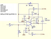
SYSTEM ONE NOISE FLOOR IMPROVMENTS.
Analogbuff
The AD797 will replace the NE5534 and usually have better noise floor.
Some of the Systems may not have much improvement in the noise floor while others will show 2-3dB better noise.
1. Run the noise test on both inputs A & B as a reference.
2. Remove the NE5534
3. Add the AD797
4. Add new PS bypass parts to back side of the PCB (CA1, CA2 & CA4)
5. Add CA3 (47pf)
6. Replace the 10pf cap with CA3 (22pf)
Note that the A and B PCB layouts are a little different.
I have also looked @ the LME49990 SOIC with DIP8 adapter and this also needs PS bypassing. No firm information yet to post.
Good Hunting
Duke
Attachments
System One to measure TUBE CIRCUITS
User Tip: Measuring High Voltages with AP🙂
A client came to me last week with this problem and he uses a System One.
The AP systems One, Two, Cascade and 2700 family have a 200 volt max input and the input to the systems are 100k // 200pf. I have made many measurements on TUBE CIRCUITS using my 100:1 Tektronix probe into my gig ohm microphone preamp. I use a BNC Tee with my 1 Meg // 20pf special load. The preamp output easily drives the AP with great bandwidth. The BNC adapter to the microphone preamp is a 22pf series cap with a 200v plus rating.
I hope may help some of your measurements.
Duke duke.aguiar@ieee.org
Hi all,
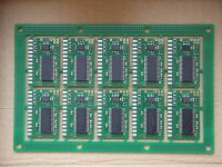
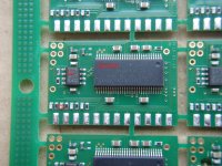
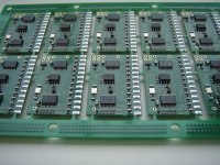
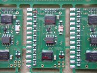
I received 20 assembled prints last week. I attached some pictures of the PCB panel with a short description what the chips are doing.
I am working at a project in Germany until the end of the week and unfortunately did not have the time to solder the connectors and USB cable and ship the interfaces. The next weekend i have some spare time and i will solder the connectors and send the first interfaces.
In comparison to the first print i changed the plating to gold flash and the thickness of the print is now 1 mm. Some minor changes in signal layout and some pin swapping were done too.
The top side has 44 components and the bottom side has 22 components, in total 68 components (hope i counted right).
Thx, Udo
Attachments
Hi all,
I received 20 assembled prints last week. I attached some pictures of the PCB panel with a short description what the chips are doing.
I am working at a project in Germany until the end of the week and unfortunately did not have the time to solder the connectors and USB cable and ship the interfaces. The next weekend i have some spare time and i will solder the connectors and send the first interfaces.
In comparison to the first print i changed the plating to gold flash and the thickness of the print is now 1 mm. Some minor changes in signal layout and some pin swapping were done too.
The top side has 44 components and the bottom side has 22 components, in total 68 components (hope i counted right).
Thx, Udo
right angled trace corners (90 deg)

Don't often see them🙂
Sorry for OT.
- Home
- Design & Build
- Equipment & Tools
- Audio Precision System Sys1 USB Interface