But not as nasty as the evils inflicted on some poor guru's tested & validated circuits. 😱Pow. Ouch! geez. Wow. slam. bam. wham. Ohhh. plop. thud. silence.
_____________________
I need to point out that I have my own reservations about eg returning feedback to the cascode junction as Self fig 8.6B from the 4th ed.
This is not from sims but from Jurassic 'real life' experience. The method looked very attractive when power amp design was really important to me. My memory is a bit dim but I think I abandoned it for overload & recovery issues rather than stability.
I also found a simple way to get its PSR advantage without its disadvantages.
This is a single NPO/COG cap to the other side of the CM as C1 in #4 tpc-vs-tmc-vs-pure-cherry or C5 in #2060 discrete-opamp-open-design
This is best with simple compensation schemes like plain Miller or 'pure Cherry'
_________________
I could go on about the evils of the cascode method ... but I don't pontificate on stuff where I've only small 'real life' experience. I won't even mention stuff where the only 'evidence' is my wonky theory or sims. 😀
If I ever am forced to use this technique, I would want to steal .. I mean improve on .. how Self does it in McLaren-Tag. I'm confident he would have found some simple way around the evils 🙂
re: post #880
'Afraid the book is already at the production stage now.
BTW, It certainly is orderable. I preordered my copy from Amazon UK
a week ago and yes, at a very reasonable price.
* * * * *
Ding!
OK, guys - cooling off period over. Back to slugging it out!
'Afraid the book is already at the production stage now.
BTW, It certainly is orderable. I preordered my copy from Amazon UK
a week ago and yes, at a very reasonable price.
* * * * *
Ding!
OK, guys - cooling off period over. Back to slugging it out!
Last edited:
Michael, if you are referring to the schematic you posted here, no simulations are required to explain why you got instabilities in the minor loop. You did not degenerate the VAS (or TIS if you prefer) - which would be highly unusual for any practical implementation.
Degenerating the TIS only compromises minor loop stability margins and has nothing to recommend it.
It's perfectly valid to sim one of Doug's 'real life' amps provided you use models as close to what he uses as possible. If you then replicate his 'real life' test results for THD & stability, you can be fairly confident your sim is within striking distance of 'real life'
This, I am afraid, is nonsense. The performance of an amplifier, of whatever topology, should not be dependent on the transistors used. You should know that.
I demonstrated to my satisfaction, many years ago, that input cascode inclusive Miller compensation is unstable because the Miller loop encloses more than two transistors, and that, consequently, the minor loop must itself be compensated.
I presume, and feel free to correct me if I am wrong, you should have no difficulty running your own simulations to verify this fact.
But if you take one of his designs and
... you only demonstrate that your choice of devices and perhaps your understanding of some very basic issues is inadequate or inappropriate.
- change ALL the devices
- resulting in operating points & currents that are well outside his recommendations
- remove several items that practically guarantee the amp will be unstable with 'real life' loads
- make other major changes to the circuit which you claim are trivial and have no effect on THD or stability .. but other gurus (eg Cherry & others) & pseudo gurus (eg me & others) feel are important 🙂
- then claim the circuit is unstable/wonky/evil
It would help your credibility even more, if you post a complete circuit of YOURS that demonstrates what you consider good practice & performance. This is preferably a 'real life' device but even a complete SPICE model would be an improvement over what you have shown so far.
This would demonstrate you have some idea of how to do a good amp. As it is, you have only demonstrated you know how to muck up someone else's design. 😱
If even YOU won't vouch for the performance of your circuits, why be surprised that other people won't waste time working on them. 😕
I have previously explained to you that my circuits are to be the subject of a future publication and will, therefore, not be posted here.
Further more your assertion that I "muck up someone else's design" is inutterable nonsense.
I have, for instance, demonstrated that your obsession with Cherry's output stage inclusive Miller compensation is entirely misguided as the scheme is unstable, and I have, moreover, given sound reasons why this is so. I showed that for the scheme to work you would need significant shunt compensation to ground at the TIS output which would merely compromise second stage linearity and the slew rate of the amplifier.
Further, I have demonstrated that your beloved TIS degeneration, recommended by Cherry supposedly to enhance major loop stability, is completely useless, and, in fact, merely degrades minor loop stabilty.
Have you actually tried to replicate or otherwise perform my simulations with the "correct" circuits and models of your choice? Hell No!

Indeed, all you've done in response is captiously cling to extraneous and wholly impertinent minutiae such as whether the quiescent TIS current differs by a few milliamps and the like, seemingly entirely oblivious to the fact that an amplifier's major loop and minor loop stability should be completely insensitive to TIS quiescent current or the degeneration resistors used in the current mirrors and other irrelevant trivia. 😕
Last edited:
Show us the sim for no degen and some degen and lots of degen.
Hi Andrew, I posted the .png of the simulations, the asc file and the models used somewhere in the Bob Cordell book thread. I am afraid I really can't be asked to run them again.
re: post #880
'Afraid the book is already at the production stage now.
BTW, It certainly is orderable. I preordered my copy from Amazon UK
a week ago and yes, at a very reasonable price.
I can't wait to get my copy. 🙂
Degenerating the TIS only compromises minor loop stability margins and has nothing to recommend it.
You can (just) get away with this in a current source loaded TIS, but in fully balanced designs that have the LTP resistevely or mirror loaded you run the risk of forcing an imbalance in the LTP - degen helps to accurately define the TIS standing current.
Degeneration of the TIS has much to recommend it in my view an especially in fully balanced designs.
Last edited:
The TIS degeneration resitor if used should be bypassed with at least 1nF capacitor to prevent it from adversely affecting minor loop stability margins.

The TIS degeneration resitor if used should be bypassed with at least 1nF capacitor to prevent it from adversely affecting minor loop stability margins.
Come on now Michael. Thousands. Perhaps millions of amps have been built without this embellishment and without any instability.
Show the sim and then lets decide if it in fact is a real world problem. I doubt it!
Did you ever see this Darlington like arrangement ? Eg No 23 . Workable as a VAS ?
http://www.diyaudio.com/forums/solid-state/74861-single-darlington-line-preamp.html#post856982
http://www.diyaudio.com/forums/solid-state/74861-single-darlington-line-preamp.html#post856982
Last edited:
Come on now Michael. Thousands. Perhaps millions of amps have been built without this embellishment and without any instability.
Show the sim and then lets decide if it in fact is a real world problem. I doubt it!
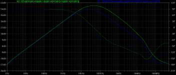
Admittedly, the loss in minor loop phase margin is small, but it is repeatable and consistent. Then again I didn't claim that it was a major problem.
The point is, the assertion made by Cherry, krglee and others that TIS emitter degeneration promotes stability in the major or minor loops is wholly incorrect.
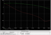
Green trace: minor loop phase shift of 153 degrees at unity loop gain frequency without emitter degeneration.
Blue trace: minor loop phase shift of 161 degrees at unity loop gain frequency with emitter degeneration of 22 ohms.
Attachments
Last edited:
But, you have to weigh that up against the fact that in non-current source loaded TIS stages without emitter degen the TIS current is ill defined, and worse, the LTP is in all likely hood in a state of imbalance. The LTP imbalance issue applies to all topologies without emitter degen BTW.
How do I know this? Because I have used the emitter degen resistor to balance the LTP and as a consequence, reduce overall system distortion.
Try it. It works.
How do I know this? Because I have used the emitter degen resistor to balance the LTP and as a consequence, reduce overall system distortion.
Try it. It works.
But, you have to weigh that up against the fact that in non-current source loaded TIS stages without emitter degen the TIS current is ill defined, and worse, the LTP is in all likely hood in a state of imbalance.
Which is one extra reason why I would generally avoid the complementary push-pull TIS.
Degenerating the TIS only compromises minor loop stability margins and has nothing to recommend it.
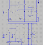
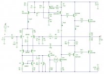
Well Michael, time is not the most precious resource for a poor EE student, so I ported your post here to PSPICE in our lab. I re-captured exactly your schematic, used the exactly the same values (although I have some concerns, like why in hell are you running the pre-drivers so hot at 25mA) and used exactly your models, as posted.
Attached are the results. For zero ohm TIS degeneration, the minor loop is definitely unstable, with an ULGF of 28MHz and a phase margin is -23 degrees. For 50 ohm degeneration, the minor loop is marginally stable with an ULGF of 22MHz and a phase margin of 1.5 degrees. Finally, for a 100ohm degeneration, the ULGF is down to 17.6MHz and the phase margin is some 22 degrees, which is acceptable for the minor loop.
Draw your own conclusions.
Attachments
Hi Andrew,
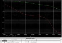
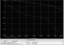
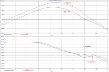
Please look here for some more plots the of gain and phase response of a TIS inner loop, one with no TIS emitter resistor (red curves) and one with a 100 Ohms emitter resistor. With RE=0, the loop is marginally stable (PM=33 degrees), though with RE=100, the circuit is more and also sufficiently stable (PM=71 degrees).
Cheers,
E.
PS: I've used Bob's models for the IPS and TIS. Models for the driver and output stage were from Fairchild. X1 is a Tian gain probe. Contrary to some other postings, everybody should be able to repeat and verify my findings.
Attachments
Well Michael, time is not the most precious resource for a poor EE student, so I ported your post here to PSPICE in our lab. I re-captured exactly your schematic, used the exactly the same values (although I have some concerns, like why in hell are you running the pre-drivers so hot at 25mA) and used exactly your models, as posted.
I have no idea why you're getting those results, as I have no idea how you run your minor loop gain simulation.
Does Pspice have a loop gain probe? If so, on what principal does it work?
Can you please use the same scales I used?
Cheers.
I have no idea why you're getting those results, as I have no idea how you run your minor loop gain simulation.
Does Pspice have a loop gain probe? If so, on what principal does it work?
Can you please use the same scales I used?
Cheers.
I use a Tian probe. I also tried the Middlebrook method (duplicate the schematic, etc...), to exactly the same results (as expected).
I can't be bothered to redo everything only for your convenience of rescaling 😀. The results, as they are, are more than conclusive.
Last night I simulated two different amplifiers, each with and without the Miller compensation fed to the emitter of the cascode transistor. I used my models.
My results indicate that there is cause for concern with the cascode Miller compensation (CMC) approach, but the impairment to stability depends on the particulars of the amplifier in which it is used.
In particular, it appears to depend on the speed and HF gain of the output stage. A more pedestrian output stage, like a double, will load the VAS at the high frequencies where this occurs to the point where it crushes the gain of the local loop. Putting it another way, the load of the output stage in any given design may effectively act to compensate this minor loop. A lightly loaded VAS will, on the other hand, invite this form of instability. Think about the AC beta at 20-40MHz of an output double using ordinary transistors and the point is clear. Even with no external load, the output Zobel will create a load.
The first amplifier had a cascoded BJT LTP IPS loaded with a current mirror and a 2-transistor single-ended VAS. It had an EF Triple output stage and two pair ThermalTrak output transistors. It had a ULGF of 1MHz. With conventional Miller compensation its closed loop response fell off smoothly out to 100MHz. With CMC there was a distinct “shoulder” in the roll-ff in the vicinity of 34MHz. This shoulder caused the amplitude to be about 7dB higher at 34 MHz than with the conventional Miller compensation. There is something going on there, but how serious it is may be up for debate.
The first take-away here is that, as I stated in the thread for my book, it is very important to simulate and measure the amplifier out to well above 10MHz, perhaps to 100MHz.
I observe that minor loop instability at high frequencies will usually be visible in some way as an anomaly in the closed loop response. Above the ULGF there is decreasing difference between the CLG and the OLG anyway. This assumes, however, that it is not masked in some way by output filtering or wiring. We are, after all, talking about frequencies in the 10’s of MHz.
The second amplifier was a MOSFET power amplifier with a cascoded JFET input LTP loaded with a current mirror and using a 2-transistor single-ended VAS. It had a single pair of vertical MOSFETs that were preceded by BJT EFs. The roll-off of this amplifier above ULGF was again relatively smooth, monotonic and well-behaved when using conventional Miller compensation. With CMC, however, it had a very nasty peak in the 25MHz region, as depicted in the attached plot.
The bottom line here is that YMMV with CMC and extra caution is required when using this compensation. Simulation of the amplifier is advisable. Wideband measurement of the amplifier is also important. It is also important that the widely varying AC characteristics of the VAS and output stage over signal swing be taken into account.
So simulation and the real world are both right in their own way, and complement each other in the design process. Also, Mike and Doug are both right in different ways. It is in fact very likely that Doug’s amplifiers do not have this problem. But we cannot make a generalization that CMC is always OK with respect to minor loop stability.
Cheers,
Bob
Attachments

- Home
- Amplifiers
- Solid State
- Audio Power Amplifier Design book- Douglas Self wants your opinions