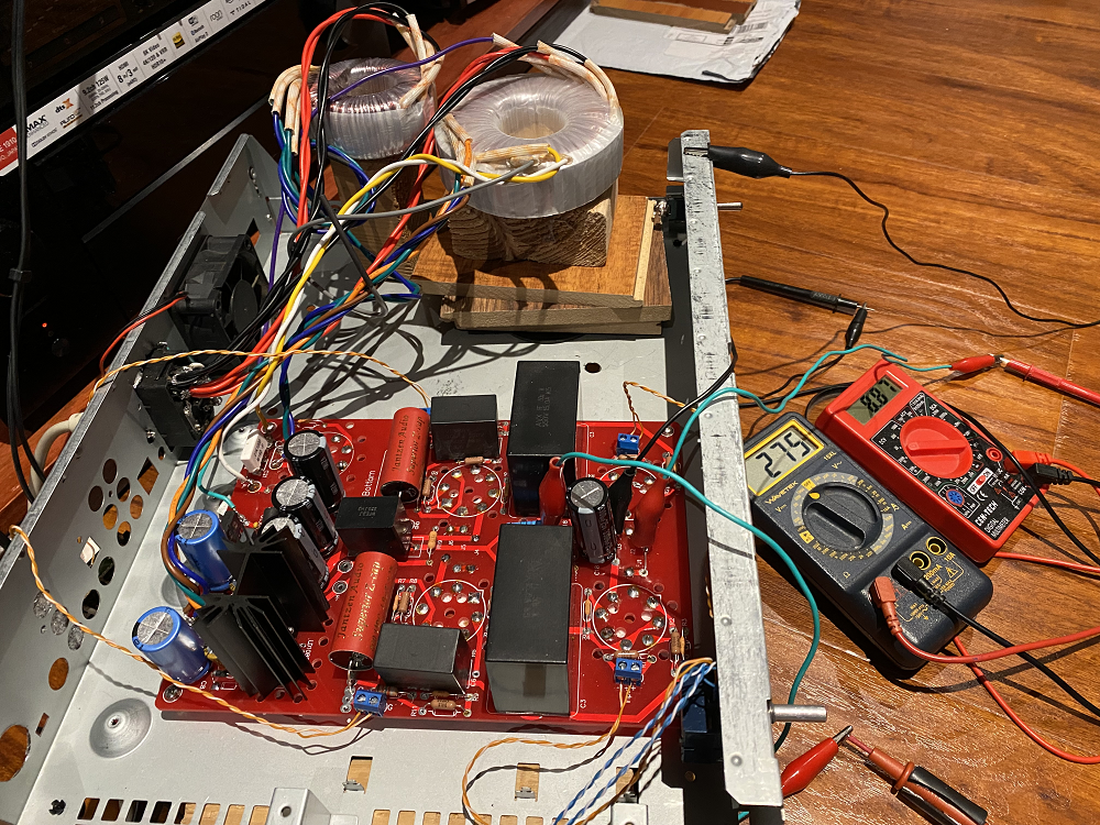
As you can see from the photo both toroidals are already moved 6+" from the PCB and they are sitting on wood and aren't near any metal. Moving the transformers and moving the wires has no impact on the hum. I do wonder if moving the IEC inlet might make a difference but I haven't tried that yet.Move both toroidals away from metal/steel at least 4 inches.
Need to ground the alps pot
Check both resistors that connect from pin 3 and 6 to the ground
What voltage at pin 7 and 8 of all tubes?
What heater voltage? either 6.xx or 12.xx
I can ground the Alps pot but the case doesn't show any continuity with any of the pins so I'm not sure what that is supposed to do.
The board has places to check various voltage levels and all are within spec. I think it uses 6.x volt heaters. Are you suggesting unplugging the tubes and measuring voltages at the socket for pins 7 and 8? Why?
I measured all of the resistors before soldering them into the board and all the resistors are in the right place.
Obviously, it would be great if there were a fix to make the SP14 quiet but Roy at VTA seemed to think this is just the way the SP14 is with high powered amps and efficient speakers. He didn't make any recommendations about changing or debugging the board. His exact words were "Most likely the hum is from too much gain in the amplifier and efficient speakers."
Clearly, it would have been nice to know that the SP14 wasn't quiet before building it but I'm not sure what level of debugging would result in a fix. That is why my question was about attenuating levels after the preamp to fix the noise issue.
I just moved the IEC power module away from the board and transformers and that didn't have any impact on the hum either. Also tried several other power outlets with no change.
It seems you are not the only one
VTA SP14 Preamplifier, your thoughts? | Audiokarma Home Audio Stereo Discussion Forums
VTA SP14 Preamplifier, your thoughts? | Audiokarma Home Audio Stereo Discussion Forums
I have a similar with your board as the link below.
toroidal is a bad idea for this design that I made mistake too but I want to fix the hum instead of try other PT. My speaker is 96 dB.
When I put the on the right side, then right speaker hum, move to left is hum on left. mount to the steel chassis with big hum. Move outside the chassis and far away from the board then the hum is gone away.
Since you mount the pot on the wood, you need to run a wire from the screw (pot) to the ground otherwise, you would hear hum and radio channel.
I don't know why one of my resistor got burn but still work. that bad resistor cause hum too.
Check DC filament +/- to make sure you have correct voltage.
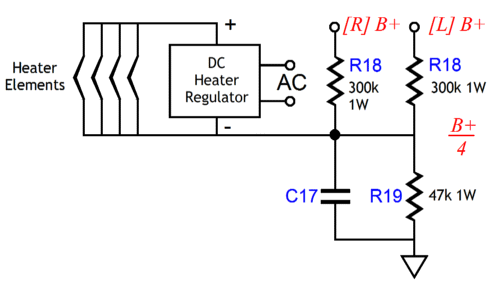
Since B+/4 where you would get 70-80v on pin 7 and 8. Measure the voltage the same way as other pins. It's cathode
Glassware Aikido All-in-One (Octal) | ACF-2 Buffer
toroidal is a bad idea for this design that I made mistake too but I want to fix the hum instead of try other PT. My speaker is 96 dB.
When I put the on the right side, then right speaker hum, move to left is hum on left. mount to the steel chassis with big hum. Move outside the chassis and far away from the board then the hum is gone away.
Since you mount the pot on the wood, you need to run a wire from the screw (pot) to the ground otherwise, you would hear hum and radio channel.
I don't know why one of my resistor got burn but still work. that bad resistor cause hum too.
Check DC filament +/- to make sure you have correct voltage.
Since B+/4 where you would get 70-80v on pin 7 and 8. Measure the voltage the same way as other pins. It's cathode
Glassware Aikido All-in-One (Octal) | ACF-2 Buffer
Good designs are built in metal casings as RF is all around us. Therefor analog electronics absolutely need shielding and RC input filters nowadays. Chassis made of wood are not suitable, they should be made out of metal.
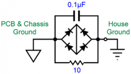
The IEC/mains filter inlet is connected directly to Audio GND. This is causing a ground loop. The metal chassis should be connected directly to PE but the Audio GND should be connected to PE via a 10 Ohm 2W resistor/diode bridge/CL60 thermistor as done in many popular devices. If you want 100% safety and you want 100% hum free, then this is the method.
In the tube DIY world many issues are introduced by the builders themselves. Like connecting chassis to Audio GND and omitting PE. Or like having tube audio with high internal voltages and no PE wall sockets. Or 3 pin IEC cables connected with 2 pin plugs... Grounding can be done the right way. It saves a lot of time troubleshooting 😀
Don't copy errors from the past to 2021 if you want stuff to behave like HiFi.
* Insertion of a superfluous high gain device is a design error and user error. It will make matters worse. If your line level signals are todays standard no gain is needed at all. You will amplify noise and ripple etc. This is the "tube magic" you are not after I hope. This situation asks for a buffer/passive approach. Attenuation of signals that have just been amplified without any reason is plain silly. I can not find the gain specifications of the VTA SP14 device as the manufacturer does not mention it! It is not a buffer for sure. You are not the only one having issues:
Help!!! Tubes4Hifi SP14 noisy
Test to prove if things are as described: use just a stereo potentiometer directly to your amplifier X and then check hum.
Last edited:
What is PE? Do you mean the power entry module? I tried the preamp completely disconnected from earth ground. Still had hum. Why would elevating the preamp from earth ground using resistor/thermistor/diode bridge be any different?
I thought CL60 thermistors required enough watts flowing through them to cause them to heat up?
Metal cases are undoubtedly good for RF but that isn't my problem.
Of course I'm building a tube preamp to add some midrange warmth/magic. The amplification of the signal is an unfortunate side effect of the design LOL.
Grounding may be also causing ground loops via source devices. You can choose denial, reluctance and assumptions. I just solve issues for tube DIYers that have a patent on hum issues, PE issues, grounding issues and GAIN issues introduced by themselves. One gets a little cynical after a while as the issues are simply always the same. The tube warmth/magic is the wish, the result is issues 🙂
PE is Protective Earth.......If you ask why elevating Audio GND from PE makes stuff different you have to look up "ground loop". PE is for safety (mandatory, not "nice to have") and it is nice for mains filters and shielding. Audio GND has no business with PE but a connection of sorts is needed when things don't go as planned.
Yes it is like taking medicine when one is healthy. Please do the simple test with just a volume potentiometer (and 4 RCA connectors) to the amplifier and you'll know where the issues come from. Only then a correct trouble solving sequence can be done.
PE is Protective Earth.......If you ask why elevating Audio GND from PE makes stuff different you have to look up "ground loop". PE is for safety (mandatory, not "nice to have") and it is nice for mains filters and shielding. Audio GND has no business with PE but a connection of sorts is needed when things don't go as planned.
The amplification of the signal is an unfortunate side effect of the design LOL.
Yes it is like taking medicine when one is healthy. Please do the simple test with just a volume potentiometer (and 4 RCA connectors) to the amplifier and you'll know where the issues come from. Only then a correct trouble solving sequence can be done.
Last edited:
The noise is there even if there is nothing connected to either of the input jacks regardless of whether they have grounding plugs or not. So far I've only used it with one input but I have used it with one or two power amps without that having any impact.
Here is a picture of the jacks. There are two input jacks (closest to the pot) and two outputs. All of the ground terminals on the RCA jacks are connected by a single bare 18 awg wire that goes in a U because it isn't possible to do it in a straight line. The VTA chassis uses different RCA jacks where the grounding terminals can be lined up with a single straight bare wire but that design still calls for a common ground between the input and output jacks and just one connection to the PCB ground. The shield of the other cable is only connected to that common ground wire although I did try it with that shield connected to the PCB ground as well and it made no difference.
Paul, looking at the pic, there is a cable from the Alps pot to the PCB. What is in that cable, only signal lines or also ground/screen?
Jan
Anyone can tell what the different from these design?
SP14 preamplifier
http://www.tubes4hifi.com/SP14.htm
AikidoOctal All-in-One: this is the one I build
Aikido Octal All-in-One
The Aikido does have house-ground circuit. However, I tried IEC ground to either one didn't make any different.

If you don't have manual, read this to understand more
New Products & Kick-Butt Audio
The Aikido uses 1 heater for all tubes at 12-12.6v while your pcb may have 2 filaments, 1 for each side.
PBC has no problem with metal/steel chassis except the toroidal, it's a loud hum when you attach to the chassis, no matter you try to shield it.
I stripped mine out to wait for aluminum chassis so i can't test now but I remember correctly you would get hum if you don't ground the volume pot. As far I can say is the hum causes by toroidal and steel chassis. Other than that, there is nothing wrong with the design. Except bad resistors, pot ground. No need RCA in/output ground to chassis. If you ground the pot to chassis but don't run the line in ground wire to the pcb, you will get a loud RF.
As I mentioned before, I got one channel hum louder than the other because a burn resistor. This design is really sensitive. I have fixed the hum of my 300B before and it wasn't bad like this one.
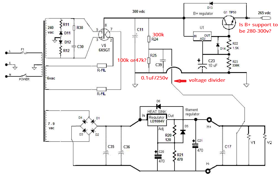
By looking at your pcb, I am not sure if it has voltage divider or not.
Took me a while to get rid of the hum. No matter you run the signal ground to the chassis, IEC ground to chassis, or IEC ground to ground house, they don't make any different. The real problem is the toroidal and pot ground.
SP14 preamplifier
http://www.tubes4hifi.com/SP14.htm
AikidoOctal All-in-One: this is the one I build
Aikido Octal All-in-One
The Aikido does have house-ground circuit. However, I tried IEC ground to either one didn't make any different.
If you don't have manual, read this to understand more
New Products & Kick-Butt Audio
The Aikido uses 1 heater for all tubes at 12-12.6v while your pcb may have 2 filaments, 1 for each side.
PBC has no problem with metal/steel chassis except the toroidal, it's a loud hum when you attach to the chassis, no matter you try to shield it.
I stripped mine out to wait for aluminum chassis so i can't test now but I remember correctly you would get hum if you don't ground the volume pot. As far I can say is the hum causes by toroidal and steel chassis. Other than that, there is nothing wrong with the design. Except bad resistors, pot ground. No need RCA in/output ground to chassis. If you ground the pot to chassis but don't run the line in ground wire to the pcb, you will get a loud RF.
As I mentioned before, I got one channel hum louder than the other because a burn resistor. This design is really sensitive. I have fixed the hum of my 300B before and it wasn't bad like this one.
By looking at your pcb, I am not sure if it has voltage divider or not.
Took me a while to get rid of the hum. No matter you run the signal ground to the chassis, IEC ground to chassis, or IEC ground to ground house, they don't make any different. The real problem is the toroidal and pot ground.
Last edited:
Point being that OP has no metal chassis where the toroid can be a problem...If a toroid transformer combined with steel chassis causes problems then there probably is something wrong by design (as it is unusual).
Please use correct terms so PE (for safety, primary side of the PSU) and Audio GND (or GND/ground) for the secondary side of PSU. "IEC Ground" and "house ground" don't make matters more clear in an area where grounding and PE already are rarely understood.
Please use correct terms so PE (for safety, primary side of the PSU) and Audio GND (or GND/ground) for the secondary side of PSU. "IEC Ground" and "house ground" don't make matters more clear in an area where grounding and PE already are rarely understood.
Last edited:
Point being that OP has no metal chassis where the toroid can be a problem...If a toroid transformer combined with steel chassis causes problems then there probably is something wrong by design.
Please use correct terms so PE (for safety, primary side of the PSU) and Audio GND (or GND/ground) for the secondary side of PSU. "IEC Ground" and "house ground" don't make matters more clear in an area where grounding and PE already are rarely understood.
True, I have to put outside the chassis or raise it up to get rid of the hum ...lol...so i decide to order the aluminum chassis.
My cynical mind says I rather have none of the issues mentioned as they outgun the benefits. What benefits exactly?
Of course troubleshooting can be done but if this design already has the reputation of being sensitive to toroids, metal chassis, being noisy and what not maybe skipping it is the best choice 🙂 The system could be analyzed and then chances are likely that no gain is needed. A simple source selector and volume control followed by a (tube) buffer, so a gain of 1, with high input Z/low output Z and power on/off muting to protect the GaN 400 device seems a better choice. Preferably a buffer that has no issues with toroids and metal chassis built in a metal casing connected to PE for safety as mandatory with devices that carry higher voltages than mains voltage. It would be a pity if the tube magic would spoil the GaN magic with over voltage that occurs at the outputs of tube circuits at power on/off. The Peachtree has no gain specified (what is it today with manufacturers?) but it has 2 x 400W output power so one does not want spikes at the inputs I think.
Still removing the device altogether and testing as suggested would make clear where the trouble comes from. The circuit you suggested works OK to fight the dreaded hum although a multi angle approach often is necessary.
Attachments
Last edited:
John Broskie design with E/I Core while I got toroid around that I thought I can use with until thing happens.
The cable from the Pot to the PCB is a silver plated twisted pair in teflon sheathed in silver plated braided copper. The two twisted pairs are connected to the middle pins of the Alps 27 pot and the two leftmost pins (looking from the rear) are tied together and the shield is connected to that and run to audio ground. The input from the DPDT switch is connected to the rightmost pins on the pot. I think I reversed the connection of the audio ground and inputs since rotating the knob clockwise reduces volume but I wouldn't have thought that would cause any problems.Paul, looking at the pic, there is a cable from the Alps pot to the PCB. What is in that cable, only signal lines or also ground/screen?
Jan
Grounding the Pot had no impact on hum.
Adding an 8 ohm 100 watt resistor (thats what I had on hand) between audio ground and power earth ground had no impact.
BUT in messing around with the potentiometer I did discover a new symptom. Turning the knob on the pot switches the amount of hum between the left and right channels. All the way clockwise the left channel has 57 dB and the right channel only 45 dB, all the way counterclockwise those values are switched. The place 3/4's around that I had it before both channels are around 55-56dB of 120 Hz hum. I didn't find a spot with no hum.
I have a 10K stepped attenuator arriving today and I'll probably swap the Alps out and put that in. At that point I'll also measure the voltages between pins 7-8 on the 6SN7 tubes.
Reading through Alashikata's post of the links to the problems people were having with the very similar Glassware Aidido design it sounded like this design is very sensitive to any mismatch between values of the capacitors or the 7 volt coils on the Antek AS-0507. Unfortunately, I had trouble following that discussing given my less than rudimentary knowledge of circuit design.
Did you get the manual with schematic? Send to me so I can compare with mine. I believe mine and yours are exactly the same design except few different in PS.
I did check all caps and resistors value before solder too, the caps don't have to be exactly the same but the resistors MUST. It's true that if one of the resistor is bad or lower value, you will get a completely different voltage on both sides. When I replaced the bad resistor on left channel, not even the voltage change in left but also change on the right as well when all resistors have same value.
So far no more hum except there is a small hum where the pot is between 95-100% which I don't turn up that high so it doesn't bother. 1/3 pot is loud. I am using ALPS 50k.
-----
The place 3/4's around that I had it before both channels are around 55-56dB of 120 Hz hum.
-----
I believe it's grounding issue because I remembered I got the same thing too.
At first, I used RJ45 network cable wires for input/output so I thought it caused the hum but changed the shield wires didn't effect at all.
When you test, make sure to keep both toroidal at least 2-3" away the pcb behind the rectifier tube. Don't let it near the 6SN7 tubes. i got hum between 1-2" next to 6SN7. What is your B+? The recommend is between 280-300v.
All I can say is the hum was caused by toroidal, ground loops, and bad resistors in my case.
I don't know if all the values are identical but you are correct, the 6SN7 part of the designs is identical. The power supply schematic does appear somewhat different.Did you get the manual with schematic? Send to me so I can compare with mine. I believe mine and yours are exactly the same design except few different in PS.
Attachments
The circuit deliberately injects power supply noise in an attempt to cancel it.
Try removing R10 and see if the noise is less or more. It will certainly be different.
Try removing R10 and see if the noise is less or more. It will certainly be different.
Why did these (non-adjustable, to make things worse) noise injection circuits become popular? It's simple enough to make a quiet B+ voltage, especially in DIY stuff with no penny pinching commercial cost constraints. Whoever thought that this was good idea? It's daft. Just say no.
All good fortune,
Chris
All good fortune,
Chris
Yours is Aikido Rev D i think. The schematic and values are for 280-300v
Do not remove R10, however; change C6 to 10uF. According to John from Aikido, he said "The higher the capacitance, the lower the noise null goes in frequency" so he told me to buy this and no problem at all.
https://www.mouser.com/ProductDetail/vishay/mkp1848c61050jk2/?qs=zDkSFN9STR99T7i7l5iS8w%3d%3d&countrycode=US¤cycode=USD
However, I just ordered this and will replace later.
Audyn Cap Q4 10uF 400V MKP Metalized Polypropylene Foil Crossover Capacitor
Does the value I listed the same as yours?
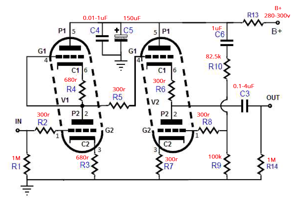
The PS does have voltage divider but I am not sure the value of R25. Mine is 47k. So when it connects at 300v, the pin 7 and 8 would be around 75-81v. At 100k, it probably shows 140-160v which it's too high. So 47k would be correct. Sorry, mine is 1 filament for 4 tubes while yours is 2 filament, 1 for each side so it may be different.
Do not remove R10, however; change C6 to 10uF. According to John from Aikido, he said "The higher the capacitance, the lower the noise null goes in frequency" so he told me to buy this and no problem at all.
https://www.mouser.com/ProductDetail/vishay/mkp1848c61050jk2/?qs=zDkSFN9STR99T7i7l5iS8w%3d%3d&countrycode=US¤cycode=USD
However, I just ordered this and will replace later.
Audyn Cap Q4 10uF 400V MKP Metalized Polypropylene Foil Crossover Capacitor
Does the value I listed the same as yours?
The PS does have voltage divider but I am not sure the value of R25. Mine is 47k. So when it connects at 300v, the pin 7 and 8 would be around 75-81v. At 100k, it probably shows 140-160v which it's too high. So 47k would be correct. Sorry, mine is 1 filament for 4 tubes while yours is 2 filament, 1 for each side so it may be different.
Last edited:
The circuit deliberately injects power supply noise in an attempt to cancel it.
Try removing R10 and see if the noise is less or more. It will certainly be different.
That's an interesting diagnostic technique - starting with the schematic and understanding it.
I doubt it will catch on...

- Home
- Amplifiers
- Tubes / Valves
- Attenuation After Noisy Preamp?