Thanks I know this page but here there is nothing written 😂😂 . I also downloaded the pdf with the diagram but I can't read it since I'm not an expert. so I was asking someone who has already soldered it the steps or where to solder.
@Matteoleon yours is not marked on the board. It seems to me that the transformers can only be attached one way, otherwise the markings would not match. maybe I'm not seeing it right.
@Matteoleon there is only one way to solder it on the PCB. If you check the pin out you will see that one pin (No. 12) is missed, you can't go wrong.
If you still have some doubt please post some picture of your stuff.
If you still have some doubt please post some picture of your stuff.
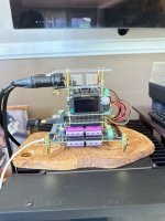
Having built a quite high-end version of Ian Canada's streamer with with shielded AC transformer + LinearPi + UCconditioners (3.3V and 5V) + StationPi Pro + FifoPi Q7 + Transport Pi AES (see photo), I am wondering what would be the ideal way to add high-end DAC functionality to the streamer.

Would it be better to feed an external DAC from the streamer (via SPDIF or I2S) or perhaps add one or more HATs in the streamer box and leverage the existing, quite sophisticated power supply?
Feedback and ideas are most welcome. Thanks in advance.
Would it be better to feed an external DAC from the streamer (via SPDIF or I2S) or perhaps add one or more HATs in the streamer box and leverage the existing, quite sophisticated power supply?
Feedback and ideas are most welcome. Thanks in advance.

@Matteoleon I think it can really be done in one way.@Matteoleon yours is not marked on the board. It seems to me that the transformers can only be attached one way, otherwise the markings would not match. maybe I'm not seeing it right.
if you are not familiar with it then post on a few pictures as @mvaldes already indicates.
https://www.audiophonics.fr/en/audio-transformer/lundahl-ll1544a-p-18893.html?search_query=Lundahl LL1544A&fast_search=fs
Attachments

@pkonstantinidis Do you have all three LinearPI stacked on top of each other?
Doesn't that makes thing too warm/hot for the ones below the top one?
Doesn't that makes thing too warm/hot for the ones below the top one?
I will be using three LinearPI. Good to know they don't run hot.
Looking at the photo, you use two 5V and one 3.3V UC? 3.3V for the clocks, 5V for the RPi4.
That'swill be my setup.
Looking at the photo, you use two 5V and one 3.3V UC? 3.3V for the clocks, 5V for the RPi4.
That'swill be my setup.
@weust Yes, as you may have seen, after the three linear power supplies (two LinearPIs and one Salas L-adapter) I have three UCconditioners, namely two 5V and one 3.3V. One 5V UCconditioner powers the StationPi Pro dirty side, the other 5V powers the StationPi Pro clean side and the 3.3V powers the FifoPi Q7 (clocks).
Nice! I need to build it together. Maybe tonight or tomorrow.
Do you plan on swapping the clocks as well?
Do you plan on swapping the clocks as well?
Hi SimonJ, I have Dac fromFinally finished my prototype full stack of Ian's modules with a Roon endpoint streamer, DAC and balanced output.
Putting this together carefully after reading all the manuals everything worked first time and sounds great. A different sound presentation to my Ian streamer with the DDDAC and I will do a full comparison in time.
View attachment 1270647View attachment 1270648View attachment 1270649View attachment 1270650View attachment 1270652
Hi SimonJFinally finished my prototype full stack of Ian's modules with a Roon endpoint streamer, DAC and balanced output.
Putting this together carefully after reading all the manuals everything worked first time and sounds great. A different sound presentation to my Ian streamer with the DDDAC and I will do a full comparison in time.
View attachment 1270647View attachment 1270648View attachment 1270649View attachment 1270650View attachment 1270652
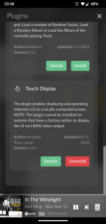
I am trying to make a Raspberry5 streamer for my Iancanada DAC, I have Raspberry5 + 5" touch screen with Volumio OS, I don't know how to make song display on screen like yours, I ask if you give some information or how to make it display on screen like yours system, thank U so much
Attachments

what type of screen do you have?
If you have a DSI screen, in most cases you only need to install the touch display plugin.
If you have an HDMI screen, you must also enter additional information in boot/userconfig.txt, Information about this can usually be found on the manufacturer's website off the screen.
touch plugin can be found under setting/plugins/user interface/touch display.
Attachments
Here is my latest DAC/streamer based on IanCanada's kit boards. I used two new items from Ian's catalog in this build; (1) the ReceiverPi DDC, and (2) the new MonitorPi Pro boards. I also used 2 LinearPis, conditioned with 2 UcConditioner Pro ultra-cap boards. One 5V, and 3.3V. I also used the venerable Dual Mono II DAC HAT, and Transformer IV as output. Since the ReceiverPI DDC was new, I'm also using a Combo384 USB interface as well. I'm planning on upgrading that to the newer, Combo768 board when it arrives. Works great with the DCC. New to this build is also a standard 5" RPi DSI screen for simplicity. One ribbon cable does it all! I'm a roon advocate so I'm also using the Roon Web Controller (RWC) extension, for transport controls and album art - used from either the front panel screen, or tablets/phones I also use as remotes.
Per my usual approach over the past couple of years, I used another mini-ITX computer case, the Goodisory A02. It was the perfect size for the kit parts I wanted to include in this build. As you can see from the images below, it was a tight fit and presented similar challenges to some of my previous builds. I haven't given it a proper listen yet, but Ian's kit have never disappointed. On the bench it sounds transparent, with high dynamics and clearly articulated notes and overall sound. I'm very pleased. Here are a few images.


Per my usual approach over the past couple of years, I used another mini-ITX computer case, the Goodisory A02. It was the perfect size for the kit parts I wanted to include in this build. As you can see from the images below, it was a tight fit and presented similar challenges to some of my previous builds. I haven't given it a proper listen yet, but Ian's kit have never disappointed. On the bench it sounds transparent, with high dynamics and clearly articulated notes and overall sound. I'm very pleased. Here are a few images.
@pkonstantinidis I'm assembling my parts and having your photo as a bit of a reference as well, I notice on your TransportPI you have J7 closed.
The documentation mentions to open J7 (remove jumpers) when using a clean 3.3V input, like you do with the Q7.
The pins on the underside of J3 (that's on my HdmiPi Pro for the 3.3V input) are longer so they connect to the one on the Q7 below it.
I had J7 closed before, and supplied a clean 3.3V from the PurePi II, and everything seemed to work fine.
Nothing melted or blew up 🙂
The documentation for HdmiPi Pro is kinda vague.
It mentioned opening J7 when using J3, but in neither example setup it's mentioned to open J7.
Just wondering what your thought it on this, or anyone else reading this, especially @iancanada.
Hi @weust
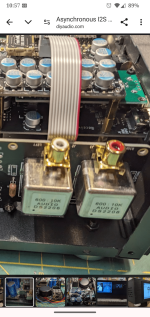
Your comment is right. I should have removed the J7 jumper of the TransportPi AES. I was doing some experiments with various ways for implementing the power supply, and I've forgotten to remove the J7 jumper. I have now restored the connection between the J3 jumpers of the FifoQ7 and the TransportPi, using short single strand cables (white and red), as you can see in the photo. I prefer using cables for connecting the J3 instead of relying on the longer pins of J3 at the bottom of the TransportPi HAT.

Your comment is right. I should have removed the J7 jumper of the TransportPi AES. I was doing some experiments with various ways for implementing the power supply, and I've forgotten to remove the J7 jumper. I have now restored the connection between the J3 jumpers of the FifoQ7 and the TransportPi, using short single strand cables (white and red), as you can see in the photo. I prefer using cables for connecting the J3 instead of relying on the longer pins of J3 at the bottom of the TransportPi HAT.
how did you get that cable for the transformers where did you buy it?Here is my latest DAC/streamer based on IanCanada's kit boards. I used two new items from Ian's catalog in this build; (1) the ReceiverPi DDC, and (2) the new MonitorPi Pro boards. I also used 2 LinearPis, conditioned with 2 UcConditioner Pro ultra-cap boards. One 5V, and 3.3V. I also used the venerable Dual Mono II DAC HAT, and Transformer IV as output. Since the ReceiverPI DDC was new, I'm also using a Combo384 USB interface as well. I'm planning on upgrading that to the newer, Combo768 board when it arrives. Works great with the DCC. New to this build is also a standard 5" RPi DSI screen for simplicity. One ribbon cable does it all! I'm a roon advocate so I'm also using the Roon Web Controller (RWC) extension, for transport controls and album art - used from either the front panel screen, or tablets/phones I also use as remotes.
Per my usual approach over the past couple of years, I used another mini-ITX computer case, the Goodisory A02. It was the perfect size for the kit parts I wanted to include in this build. As you can see from the images below, it was a tight fit and presented similar challenges to some of my previous builds. I haven't given it a proper listen yet, but Ian's kit have never disappointed. On the bench it sounds transparent, with high dynamics and clearly articulated notes and overall sound. I'm very pleased. Here are a few images.
View attachment 1333424View attachment 1333425View attachment 1333426View attachment 1333427View attachment 1333428View attachment 1333429View attachment 1333430View attachment 1333431View attachment 1333432View attachment 1333433
Attachments
@gizmo3, I happened to have some 10-conductor ribbon cable, so I bought the connectors from Mouser and made my own lengths that I needed. They're not that hard to make. A good pair of pliers is all you need. You can also find fixed lengths on eBay here. I've had to use these cables in the past, where I needed to locate the I/V board off the RPi stack. Just make sure you get the orientation correct.
Basic question but I can't figure it out...what's the polarity on j5 (3.3v) on fifopi? I'm trying to power from purepi and don't want to reverse polarity but it's not marked and I think the position is reversed from purepi.
Also...I'm supposed to connect fifopi ground to the earth on station pi....I guess I don't actually know where to connect it on fifopi...the (-) on j5?
Also...I'm supposed to connect fifopi ground to the earth on station pi....I guess I don't actually know where to connect it on fifopi...the (-) on j5?
Thanks, I'll see if I can buy some somewhere.@gizmo3, I happened to have some 10-conductor ribbon cable, so I bought the connectors from Mouser and made my own lengths that I needed. They're not that hard to make. A good pair of pliers is all you need. You can also find fixed lengths on eBay here. I've had to use these cables in the past, where I needed to locate the I/V board off the RPi stack. Just make sure you get the orientation correct.
- Home
- Source & Line
- Digital Line Level
- Asynchronous I2S FIFO project, an ultimate weapon to fight the jitter