
Thank's@zabloc Conglatulations!!! It looks magnificent. Sonic impressions?
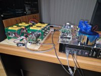
This is an alpha test, just connected to see if everything is ok.
At the weekend I will go for an initial test to see if everything behaves as it should, then planning the housing.
God help me.
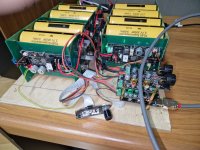
with 2000 Amps 😱that can really trigger sparks 😵
This will be 2 components, as you can see.
Streamer separate from DAC. It is very interesting that this monster of a DAC when I put it in the case will not be bigger than 400x400x150 mm.
But it will be very heavy, which I don't mind for a DAC.
Streamer separate from DAC. It is very interesting that this monster of a DAC when I put it in the case will not be bigger than 400x400x150 mm.
But it will be very heavy, which I don't mind for a DAC.
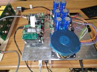
Finished version 1.2 of the UcPure holder. Small changes with a bigger base, larger flanges and holes for the wire to the balanced board were made. Not all was really necessary, so and updated and slightly narrowed V1.3 is in the making.
I am using some small M3 vibrating dampers under the PCB. M3 Dampers
They are actually really great and much softer than expected providing some movement and hopefully absorbs some vibration. Does it matter to improve SQ? Don’t know🙂
Still a great fit with 4 pieces for the UcPure.
I’ll expect to use them under my StationPi as well.
Last edited:
Stefano found the issue and solution….Yes, this is how it looks
compltely changing my streamer setup, Rock, Roon, RPI with Ropieee is for now a bridge to far, just to do some tests of course.
any way, Stefano is very supportive and we are looking to see what could cause the main issue of the Stefano DAC not working as expected. It works on my AP whee I can meddle around with timing and I2S signals…
Point is that for his Logic to work, the BCK going down must occur after the LR status changed
For chips working with I2S this is normally no problem as all is BCK up related
Also the background why in my case 31 cycle long words worked. In fact still 32 as my clock was a bit earlier as expected
Now, when the BCK is a bit delayed, it works fine. This is easy to do with two inverting gates in series.
Good support from Stefano…
Hi
I have the UcPureMkIII ultracapacitor power supply, UcBalancer protection board KIT and two Eaton XL60-3R0308T-R (3.0v) in the mail that is going to power the FifoPi Q7II.
The way I understand it, the UcBalancer should be 2.7v default mode, and the UcPureMkIII in 3.3v mode by shorting s2,s4 and s6 on the back of the PCB with solder balls.
The manual says jumper settings. but can't see any jumpers in any of the pictures I've seen?
is this correct🤔
Regards Roy
Thanks for the quick reply Crossride👌 And then I just leave the UcBalancer protection board in 2.7v default mode🤔
I have a q for the brain trust! My buddy loved my Dac so much he wants one, so I’m helping with his layout.
Can you use the FifoQ7 HDMIPI pro and the ESS dac together?
He wants to have external and internal options.
Can you use the FifoQ7 HDMIPI pro and the ESS dac together?
He wants to have external and internal options.
DIY Audio
Hi All,
I have an odd problem that I would appreciate help with. I have built a streaming DAC using all IanCanada parts.
StationPi
FifoPi Q3
Dual Mono DAC
OPA861
As I have a healthy appreciation of my own limitations I am not messing around with transformers or ultra capacitors. I am using an unused Allo Shanti linear power supply to power the clean and dirty sides of the StationPi. I then have four (yes, four!) iFi Smartpower SMPS’. Two at 5 volts powering LifePO4 Minis, one for the FifoPi, the other for the DAC board. The remaining two power the LinerPi Dual that gives power to the OPA861.
I have an ESS controller and a MonitorPi to complete the build.
Now here’s the problem. The “breadboard” build went well, with everything working as expected. I then bought a case and spent quite a while putting everything in it and creating the holes in the aluminium back panel for the various power sockets and holes for the OPA XLRs and RPi RJ45 Ethernet connector to poke through. When I power up the build inside the case, I get a problem whereby only one side of the LinearPi Dual will power on properly. The LEDs on the other side flash on and off slowly and are clearly not lighting up fully. Everything else works fine. I can actually get sound out of the DAC, but it is distorted.
The weird thing is, if I take the back panel off and connect the wires up through the open back, letting them just dangle out of the cavity, everything works fine and I get lovely sounds.
I ansssembled all my own wiring and soldered them to standard dc connectors. I hand carved the holes in the aluminium case for the various connectors then gave it a coat of Matt black rattle can paint to hide the scratches I created in the process. I checked with a DMM that I hadn’t used conductive paint.
I’m a bit stumped, any advice or pointers would be appreciated!
Hi
UcBalancer manual says.... Please note, for 3.3V and 5V applications, I don’t suggest using the 3V configuration even you have 3V ultracapacitors.
can someone explain why 2.7V default mode is recommended even you have 3V ultracapacitors🤔
UcBalancer manual says.... Please note, for 3.3V and 5V applications, I don’t suggest using the 3V configuration even you have 3V ultracapacitors.
can someone explain why 2.7V default mode is recommended even you have 3V ultracapacitors🤔
@Philip Kent
I would double check all your solder joints for cold solder joints. They should be smooth and shiny not a dull silver ball.
I would double check all your solder joints for cold solder joints. They should be smooth and shiny not a dull silver ball.
Last edited:
The 3v setting is for 15v power suppliesHi
UcBalancer manual says.... Please note, for 3.3V and 5V applications, I don’t suggest using the 3V configuration even you have 3V ultracapacitors.
can someone explain why 2.7V default mode is recommended even you have 3V ultracapacitors🤔
for 3.3v and 5v ultra capacitor power packs 2.7v is the right setting for UcBalancer.
When you are making up a 15v ultra capacitor power packs you need to have the UcBalancers set to 3V
- Home
- Source & Line
- Digital Line Level
- Asynchronous I2S FIFO project, an ultimate weapon to fight the jitter