Anything on an FFT that is not PSS (Periodic Steady State) will tend to look like noise. You can have a sine wave sweep across the audio band in the time it takes you to acquire an FFT. In that case the swept sine wave will look like noise. Doesn't mean it sounds like noise to a human.
Even pure white noise can look flat on an FFT, but that doesn't mean it sounds smooth. It can sound like popping or sizzling like frying. Why? Because of the relative phases of the noise frequencies. The probability of what phases you will get depends on the shape of the tails of the bell curve that describes the noise production process statistics.
Even pure white noise can look flat on an FFT, but that doesn't mean it sounds smooth. It can sound like popping or sizzling like frying. Why? Because of the relative phases of the noise frequencies. The probability of what phases you will get depends on the shape of the tails of the bell curve that describes the noise production process statistics.
Can you show an example where all those things were well controlled and batteries ended up sounding worse?Once all those things are well controlled, then batteries usually end up sounding worse.
Some years ago I tried LiFePO4 batteries myself for AVCC in an ES9038Q2M dac. Sounded awful. Went right back to the mediocre voltage regulator. Some years later I discussed the matter with a successful full-time professional audio designer. He didn't like the sound of batteries either. IMHO, there are times when batteries make a lot of sense though, maybe for a LNA in a can they would be ideal.
Ok, you probably prefer noise as that would be the outcome with mediocre voltage regulator on ES9038Q2M AVCC.
What the really difficult performance for a good power supply are the noise closed to DC and the low frequency flicker noise. It would be similar to the phase noise performance of a clock. (For power supply we can consider the carrier frequency is 0Hz). That's exactly the weakness of a low noise LDO or regulator.
The best power supply so far is the pure ultracapacitor power supply (in class-A mode), and then, followed by the battery power supply. High frequency ESR normally need to be taking care by local decoupling networks.
A great power supply is really significant to get the maximal out of a good clock. That's why people feel more improvement after upgrading the power supply for the clock and transport.
Ian

Agreed. Have found that to be quite true.A great power supply is really significant to get the maximal out of a good clock. That's why people feel more improvement after upgrading the power supply for the clock and transport.
Would also agree some LDOs sound awful despite their published measurements. Not all of them though.
Some other tests here also:Some years ago I tried LiFePO4 batteries myself for AVCC in an ES9038Q2M dac. Sounded awful. Went right back to the mediocre voltage regulator. Some years later I discussed the matter with a successful full-time professional audio designer. He didn't like the sound of batteries either. IMHO, there are times when batteries make a lot of sense though, maybe for a LNA in a can they would be ideal.
#67
#68
I haven't yet found a reg (and i have tried many) that subjectively beat the battery setups.
What are you doing for the decoupling networks? That, and using the wrong power transformer, the wrong regulation design, the wrong layout, the wrong buffering, wrong clock output loading, etc. can all affect clock performance.
Regarding clocks, some of the lowest phase noise clocks in the world run on regulated power. It can be done.
Regarding batteries and ultra-caps, if you still have wiring between the power supply, connectors, etc., you may still have a less than optimal power supply design. Having the final power source very near the clock, on the same ground plane, etc. can count for a lot if its done properly.
Last edited:
The issue with "can be done" is most of what is available in kit form to part-time diyers doesn't subjectively beat what they have managed to do with the batteries. Ultimately, that's what dictates what people will use. As Jackinnj showed, the batteries aren't as bad as people initially theorized they were. Then you have to account for how many people tried various regulator schemes and subjectively preferred the battery or supercap supplies.
Vref of DACs is just as important. High 1/f noise on Vref (or AVCC in ESS DACs) will end up at DAC output. The Vref power source should be located as close to the DAC Vref pins as possible so batteries, supercaps or LDOs hanging from wires do not work well.
Agreed. I would add that the clock power supply and the AVCC power should not be the same power supply. Each Vref, one for left and one for right, and the clock power supply should all be independent of each other. Using a single power supply and decoupling networks to try to isolate loads is IME usually a significant compromise.
Hello,
Why you hardly hear anyone talking about the complete partlist responsible for the esr of the complete supply. Everyone bragging about using cables useful for charging car batteries and then connecting it to a flimsy connector. Show it to a serious technician and tell him your goal is the lowest esr possible.
Once you have got everything working ditch the connectors and connect a nice cable with soldering joints right at the board.
Have asked it before should these cables be routed like ac cables close to chassis, no loops, twisted? Of course there is no money to be made paying attention to this. Sure throw in an extra pair of supercaps.
Greetings Eduard
Hello,Vref of DACs is just as important. High 1/f noise on Vref (or AVCC in ESS DACs) will end up at DAC output. The Vref power source should be located as close to the DAC Vref pins as possible so batteries, supercaps or LDOs hanging from wires do not work well.
I use the DDDAC and the soon to appear improved boards will have an updated supplies right where they should be next to the " consumer ".
That is why i decided to have the 5 volt supply ( dirty side of the Q7) right at the board using a 5 volt Tent shunt supply right where it needs to be on the board where the 5 volt input connector used to be. Of course this is not the most important supply but it is easy and cheap to get it right.
Not sure but a power supply also needs to work both ways and stop getting dirt into your wall socket?
Just curious Eduard
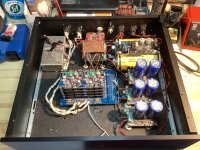
You might try putting a big, full height, 18-gauge steel plate across the inside of the case to seal off the dac from the RF coming from the RPi and the USB board. Maybe where the red line is below:

It depends though. I would have to hear the dac to say how far off it is.
Maybe even better to put a steel divider or maybe a thick copper divider around the RF source area:

The difference between steel and thick-enough copper is that steel is lossy, and copper is reflective. With a box that close around some of the components I would probably rather see copper. It should be a few to several skin-depths thick at the lowest frequency of interest. The box should ideally not have any holes in it at all. In reality it will need some opening for wires to get in and out. Try to keep those openings to a minimum and consider they will form antennas. Make sure they don't radiate where you don't want RF going.
Also, don't know how you are clocking the dac. Hopefully the clocks are very close to the dac and you are sending a buffered copy of the master clocks to the RPI and USB stuff to keep the system synchronous.
In addition, I2S signals are definitely RF. Running single wires with one shared ground is asking for trouble.
It depends though. I would have to hear the dac to say how far off it is.
Maybe even better to put a steel divider or maybe a thick copper divider around the RF source area:
The difference between steel and thick-enough copper is that steel is lossy, and copper is reflective. With a box that close around some of the components I would probably rather see copper. It should be a few to several skin-depths thick at the lowest frequency of interest. The box should ideally not have any holes in it at all. In reality it will need some opening for wires to get in and out. Try to keep those openings to a minimum and consider they will form antennas. Make sure they don't radiate where you don't want RF going.
Also, don't know how you are clocking the dac. Hopefully the clocks are very close to the dac and you are sending a buffered copy of the master clocks to the RPI and USB stuff to keep the system synchronous.
In addition, I2S signals are definitely RF. Running single wires with one shared ground is asking for trouble.
Last edited:
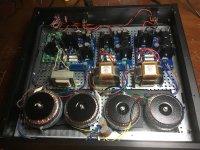
Hello, you could try twisting the ac wires coming from the transformers and letting them run towards the power supply boards on the right side. Now the choke is kind of surrounded by ac wires which is probably a bad idea.Main psu
All the power supply connections seem yo be rather long.
Of course you could also go for choke input, remove the 7810 regulators and not use the regulator at all.
Or just wait for the mk3 Dddac!!
When i am back home i will design a seperate box for the Raspberry and get it connected with hdmi. It seems to be the biggest offender in the box
Greetings Eduard
Thx Markw4.
There is no rpi in the dac. I use Aurender streamer. Every i2s wire have it’s own ground wire, and I have soldered all of them for maximum connection.
FifoPi Q7 with Ian’s new sc clocks works it’s magic under the copper shield. I think it is important that the hook up cables from UcPure and the supercaps boards are as short as possible.
I will buy new cabinets and place everything as optimal as possible, and also work on shielding.
eduard@
I have removed the 7810 regulators, and have 10vdc on input mainboard. Rock steady for many years.
I have removed the 7810 regulators, and have 10vdc on input mainboard. Rock steady for many years.
- Home
- Source & Line
- Digital Line Level
- Asynchronous I2S FIFO project, an ultimate weapon to fight the jitter