Hello,
If things did not work you switch it of , change nothing. Then you switch it on again and then things do work.
Sounds weird or not?
Maybe some caps not fully charged. Maybe something needed re booting.
If you switch it of tonight will it still work tomorrow?
Greetings Eduard
If things did not work you switch it of , change nothing. Then you switch it on again and then things do work.
Sounds weird or not?
Maybe some caps not fully charged. Maybe something needed re booting.
If you switch it of tonight will it still work tomorrow?
Greetings Eduard
.......with software rebooting is king and normal troubleshooting process. This process is so common in todays world
Hello,
I am outside my country so not to read manuals. But if i remember correctly there is also delay during start up necessary between certain circuits in order to make them work properly. Or was that related to Raspberry on one side and the Canadian pile on the other side?
Usually my Roon device, Dddac, raspberry and the Canadian stuff always powered up. But of there would be a power rupture for a minute it should power up correctly when power is back. If not Ian should make a proper start up board and not a new updated board.
Greetings Eduard
How did you manage the USB C port to power the button ? Could you provide a picture, please ?I solved it by powering the button light continuously from the 5V RPi PS. And pushing the button takes the PurePi out of standby.
One suggestion i would have is cover a couple of projects from the project page. If the intention here is to help newbies then a step by step guide with pics will be very helpful. A debugging section would also be very important.I started a blog for Tips of DIY digital audio projects.
https://iancanada.ca/blogs/news
I'm still working on adding more.
Please let me know if you have any tips to share.
Thanks,
Ian
Maybe one such guide for Compact size project and one for flagship full size project would ideally cover 95-99% of all help requests.
One critical thing missing IMO is how to use UCPure with these projects. An optional section with integration with UCPure will i think cover all the bases.

I am not using the USB C port, but connected the button to J3 of the StationPi Pro. Currently making changes again, so no picture.How did you manage the USB C port to power the button ? Could you provide a picture, please ?
Not sure where to post this. I just recently bought an Ian Canada system including a PurePi II, Monitor Pro, ReceiverPI DDC, 9038Q2M Dual Mono II DAC, and FifoPI Q7. I built it following the Gabster D6 build except that I added the ReceiverPI. I finally got the system working and was listening to everything last night and it was wonderful. All of a sudden the sound changed alarmingly. There was huge amounts of static, the sound only came out of one speaker and you could barely hear the music underneath all of the noise. I did nothing to change anything. If anyone has any insights I would be most greatful. I am really upset about this build.
@theaddies
Please no worries, I'm here to help. Can you please send a picture of your system showing the configuration and connections, to me at iancanada.mail@gmail.com. Let me try to figure it out.
Ian
Please no worries, I'm here to help. Can you please send a picture of your system showing the configuration and connections, to me at iancanada.mail@gmail.com. Let me try to figure it out.
Ian
In case anyone is still interested, the conundrum is solved.Hello Ian, I’ve been fighting with this for a week now, and I am sorry to report it’s still not working. The clocks do light up now, and switch depending on the input, but there is no output from the optical (haven’t tried the coax) . Plugged into each other everything works fine. I think I’m going to abandon this and find another solution do connect everything.
The stationpi-transport combo does NOT work with the Pi 5. As soon as I replaced the 5 with a 4 everything worked. (note : it doesn't even work with point to point wiring)
I have a sneaky suspicion it has to do with the higher power demands of the 5, and the fact that if the system does not detect the new 5A power brick designed for the 56 on its USB-C input, the 5 switches to some sort of 'low power mode'. The 5 can be tricked into going full power regardles, but as I am using Ian's 2.5A linearPi's I didn't see the point.
Next stop is getting the Waveshare to work with Volumio.
Pete
@landiepete,
That's a really interesting report. RasrberryPi 5 is not yet available in Canada so I have no chance to test so far.
Once I have a RPi5, I'll do a test and post a update.
RPi power consumption keeps increasing. That means the EMI noise has been increased. In my won configurations, I started to use the RPi externally with an isolator the HdmiPi. And then connect to the ReceiverPiPro or DDC through the HDMI cable. Ground loop was cut and the EMI noise eliminated significantly. RPi no long needs a good power supply because of the isolation, standard USB power addapter would be OK.
Please refer to the #91A RPi free streamer transport configuration:
https://iancanada.ca/products/flags...-re-clock-ddc-streamer?variant=47598243610924
Please keep us posted.
Thanks,
Ian
Hello,
It seems it is kind of hard building something that will work and keep working.
Maybe building should take place exactly according to the manuals.
Digital keeps amazing me with the number of things that can go wrong or will go wrong after some time.
Of course the higher the number of boards the bigger the chances of something bad happening in a tiny area that will mess up things.
We have read about the 325F caps needing the right soldering tool. But surely not everyone will buy one for just making 6 joints. They will say, look i did manage to do it with my 60 watt tool and it works. And then suddenly a cold solder joint will cause problems and they will have no clue what is wrong.
Spend a fortune on clocks sure but the right tools no way. Sure a Knipex set of pliers is not cheap but every time you use it makes you happy.
I dont have the complete set but have a few. But the one set special for electronics has reduced dimensions so easier for small spaces. The bigger ones only useful when you need to apply some force. Usually not use any force with modern days circuits boards
Greetings Eduard
Thank you Ian and jrocke.
Finally clear sound came out.
https://www.diyaudio.com/community/...st-tht-i2s-input-nos-r-2r.354078/post-7557929
Finally clear sound came out.
https://www.diyaudio.com/community/...st-tht-i2s-input-nos-r-2r.354078/post-7557929
Hello,
RPI power consumption keeps increasing. That means the EMI noise has been increased. In my won configurations, I started to use the RPi externally with an isolator the HdmiPi. And then connect to the ReceiverPiPro or DDC through the HDMI cable. Ground loop was cut and the EMI noise eliminated significantly. RPi no long needs a good power supply because of the isolation, standard USB power adapter would be OK.
After reading this all serious audiophiles should agree that an no RPI should be in the vicinity of serious audio gear. Just like the notorious Italian designer told us before.
So power the RPI with a standard grade supply. Put in some kind of alu stomp box , add some copper shielding, add the board that will gave the RPI a hdmi output. That board of course need a nice supply ( but after comparing the specs from the supercaps to the specs of the green board terminals i need some salt)
The only connection between this stomp box and Ians stack will be a normal hdmi cable so nothing to go wrong there.
Greetings Eduard
Hi Eduard
Its great you think nothing will go wrong with the HDMI type builds. I am going that way.
If I had my way I would not use a Raspberry Pi, for me there are too many Raspbeery software options not to them.
Happy New
Eddie
Its great you think nothing will go wrong with the HDMI type builds. I am going that way.
If I had my way I would not use a Raspberry Pi, for me there are too many Raspbeery software options not to them.
Happy New
Eddie
I had to buy a 100w solder iron for use with even the smaller caps.How are you struggling?, I had to go out and buy a Large soldering Iron to get it to work correctly my Normal soldering Iron made a mess of Things,, If you have not done soldeing before , see if someone in an electrical or plumber store near you can do it https://www.amazon.co.uk/gp/product/B09CZ2W99J/ref=ppx_yo_dt_b_asin_image_o05_s00?ie=UTF8&th=1 ,
Hello,
Solder containing lead will usually also make things easier.
And a fixed position of the cap and board, allowing you to add some pressure for better heat transfer is necessary.
Greetings, Eduard
Solder containing lead will usually also make things easier.
And a fixed position of the cap and board, allowing you to add some pressure for better heat transfer is necessary.
Greetings, Eduard
@landiepete,
That's a really interesting report. RasrberryPi 5 is not yet available in Canada so I have no chance to test so far.
Once I have a RPi5, I'll do a test and post a update.
RPi power consumption keeps increasing. That means the EMI noise has been increased. In my won configurations, I started to use the RPi externally with an isolator the HdmiPi. And then connect to the ReceiverPiPro or DDC through the HDMI cable. Ground loop was cut and the EMI noise eliminated significantly. RPi no long needs a good power supply because of the isolation, standard USB power addapter would be OK.
Please refer to the #91A RPi free streamer transport configuration:
https://iancanada.ca/products/flags...-re-clock-ddc-streamer?variant=47598243610924
Please keep us posted.
Thanks,
Ian
I think what the ecosystem needs is some kind of power distribution system for the pi and the modules. The use of the infernal USB-C plugs for HATs, PI's and associated devices in general does not make for an elegant solution in a HIFI like enclosure.
I don't generally like the enormous stacks of HATs.
I think I'm going to try and figure something out with the Station PI with a flatcable attached to the HAT side, and the HATs themselves in a separate section of the enclosure. I also need to find a way to elegantly break out the Pi USB, HDMI and so on to the rear of such an enclosure.
Furthermore I think that although power supplies are important, far too much community attention goes to ever bigger batteries, supercaps, more supercaps, supercaps with batteries, and so on.
In the mean time, it's a plank with a touchscreen !
Hello,
These supercaps with ultra low esr should be " doubled " to reduce esr to a total that will be much lower and then be connected to the green terminal on the board. Take a look at the specs of these terminals and ask a ten year old kid to calculate how much esr you will have from solder joint on one board to the joint on the other board.
Right now i am in Vietnam so impossible to ask a kid to add things up because my Vietnamese skills are to low.
If the kid is a little smart he/she will notice something is a bit weird.
Greetings Eduard
I don't know if anyone has already suggested this, you need to fix this.Hi Guys,
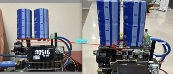
Need a bit of help. I assembled the DDC without RPi. But after powering on, the MonitorPiProII id not turning on. Any ideas what might be going wrong hereView attachment 1253418View attachment 1253419View attachment 1253420View attachment 1253421View attachment 1253422View attachment 1253424
is just a well-intentioned tip.
Attachments
- Home
- Source & Line
- Digital Line Level
- Asynchronous I2S FIFO project, an ultimate weapon to fight the jitter