No.
Not.
I'll remember to make a meaningful attack next time 🙂
//
I don't want this thread to be closed as well so I avoid replying to you.
If, on the other hand, you write something that makes sense from a technical point of view, I will be happy to read it and answer you.
IMO it’s better to place the FiFo after the DSP so you don’t mess up the reclocked signal
Thanks, but let me rephrase my question like this - can the non-reclocked signal from RPi have a negative impact on DSP calculations that will persist even if the signal is reclocked after DSP?
Also if DSP is using XO master clock does that mean the RPi signal is actually being reclocked on entering the DSP?
Thanks.
I guess not but I’m not certain about that. Maybe someone with a better inside in the DSP process can help you
I don't want this thread to be closed as well so I avoid replying to you.
If, on the other hand, you write something that makes sense from a technical point of view, I will be happy to read it and answer you.
Thank you!
//
Because when the noise floor is reached the plot becomes flat.
Yes, but there is still an area under this "flat", which translates to additional jitter, isn't it? And I would think the AD recommendation is not to be ignored. Maybe the phase noise has a sharp rise somewhere in the MHz range?
The broadband phase noise does not affect much the jitter, the jitter is mainly affected by the close in phase noise as demonstrated shifting the integration bandwidth lower limit from 1Hz to 0.1Hz in a previous post.
This is maybe true for your oscillator, but perhaps not for the sine to square converter. As I mentioned before, the square wave phase noise energy is in the harmonics, which the timepod can barely see (essentially, only the low order harmonics are visible to the timepod due to the input filter) and even so, as expected, a 10db and over increase in the wideband phase noise is already visible on your plots. I don't think, given the circumstances, that limiting the integration bandwidth to 100KHz is showing the truth about your square wave jitter. BTW, I don't think anything much better than yours can be executed using your approach (and I also think Ian's version won't get much better or worse in an apple to apple comparison). It's only your statement that "square conversion doesn't affect the jitter" that I find incorrect and and attempt to oversell your solution.
It's quite obvious that moving the integration bandwidth to lower frequencies such 0.001 Hz the jitter increases dramatically, but you should know that to measure down to 0.1Hz from the carrier the cross correlation takes several hours to do the job (8 and more).
So what would be the benefit?
For the purpose of this discussion, how long a measurement takes is irrelevant. What is relevant is how much good is good enough? You apparently decided that integrating from 1Hz for the purpose of jitter calculation is good enough, how come? Perhaps integrating from 0.001Hz (resulting in how much more jitter?) would be relevant for the scope of digital audio? Or maybe a jitter value obtained by integrating from 100Hz (for which nobody would need a timepod to measure, a spectrum analyzer or even a digital scope would be perfectly fine) would be good enough?
We are talking about measurements comparison between a phase noise analyzer and a digital oscilloscope which cannot measure at such close in frequencies to the carrier Since it has a poor time base and does not use cross correlation.
You have a point here, I agree a digital scope cannot estimate these levels of phase noise down to 1Hz, but then see above; the core question still remains what's good enough for audio purposes? One think I am pretty sure about: the close in phase noise is not audible, at least because the source material processing wow and flutter (even if it's not sourcing from mag tapes) is many orders of magnitude higher. If the entire processing chain would use your clocks, then we may talk about a Crystek oscillator in the DAC as being "poor" (and even then, the effect would be beyond any human hearing threshold).
Last edited:
Yes, but there is still an area under this "flat", which translates to additional jitter, isn't it? And I would think the AD recommendation is not to be ignored. Maybe the phase noise has a sharp rise somewhere in the MHz range?
I don't believe, when the noise floor is reached the phase noise keeps constant.
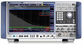
Please take a look at the FSWP attached picture.
It's the phase noise plot of a 100MHz oscillator, above 10 kHz from the carrier the phase noise is almost flat.
Please, note that the measurement have been executed with an offset band 10Hz to 300kHz
This is maybe true for your oscillator, but perhaps not for the sine to square converter. As I mentioned before, the square wave phase noise energy is in the harmonics, which the timepod can barely see (essentially, only the low order harmonics are visible to the timepod due to the input filter) and even so, as expected, a 10db and over increase in the wideband phase noise is already visible on your plots. I don't think, given the circumstances, that limiting the integration bandwidth to 100KHz is showing the truth about your square wave jitter.
As I have said even the R&S FSWP uses a LPF around 30 MHz (with down conversion) and the upper limit of the integration bandwidth to measure the jitter of a 100MHz oscillator was 300kHz, as in the attached picture.
BTW, I don't think anything much better than yours can be executed using your approach (and I also think Ian's version won't get much better or worse in an apple to apple comparison). It's only your statement that "square conversion doesn't affect the jitter" that I find incorrect and and attempt to oversell your solution.
Indeed, as I have already said, we will use a totally different approach to design the sine to square converter of our top system (the famous spreadsheet).
For the purpose of this discussion, how long a measurement takes is irrelevant. What is relevant is how much good is good enough? You apparently decided that integrating from 1Hz for the purpose of jitter calculation is good enough, how come? Perhaps integrating from 0.001Hz (resulting in how much more jitter?) would be relevant for the scope of digital audio? Or maybe a jitter value obtained by integrating from 100Hz (for which nobody would need a timepod to measure, a spectrum analyzer or even a digital scope would be perfectly fine) would be good enough?
Since someone did ask me to compare my measurements against the measurements from a digital oscilloscope and I have a noise spectrum instead of a standalone number, I had to
choose an integration bandwidth to calculate the jitter from the phase noise.
The digital oscilloscope does not provide the noise spectrum and I assumed its time base is very poor, so I have chosen 1Hz instead of 0.1Hz or even 0.01 Hz from the carrier.
The calculated jitter of the Crystek CCHD-957 I have published has clearly demonstrated that the the digital oscilloscope cannot measure at such close in frequencies, since its measurement was more than 2 order of magnitude optimistic than the actual jitter of the oscillator.
I suspect that the digital oscilloscope cannot measure the noise below 100 Hz from the carrier.
You have a point here, I agree a digital scope cannot estimate these levels of phase noise down to 1Hz, but then see above; the core question still remains what's good enough for audio purposes? One think I am pretty sure about: the close in phase noise is not audible, at least because the source material processing wow and flutter (even if it's not sourcing from mag tapes) is many orders of magnitude higher. If the entire processing chain would use your clocks, then we may talk about a Crystek oscillator in the DAC as being "poor" (and even then, the effect would be beyond any human hearing threshold).
I'm not sure, the answer arrives as soon we wil find the time to build an up-converter to measure the phase noise at the output of the DAC in audio band.
On the other hand, if the close in noise did not affect the digital to analog conversion the device offered in this thread would be useless because its purpose is just to fight the jitter using a FIFO wich reclock the signals in a different time domain using a far better master clock than the one of the source.
Attachments
I don't believe, when the noise floor is reached the phase noise keeps constant.
Yes, maybe it is remains constant (but then again, maybe not), but the jitter (the phase noise integral) is not, in particular for non sine signals. Which raises a good question, what matters for audio, the phase noise (frequency domain), or the jitter (in the time domain)? You seem to conveniently switch from one view to another, depending on the context. It would be nice to once and for good specify the scope of your project(s).
For the rest of my questions and concerns I did not find any relevant answers in your post. Beyond using correlation to cancel out the correlated noise sources, the Rohde FSWP is a different phase noise measurement principle, so comparing with the timepod is not apple to apple. Also, rubbing the digital scope limitations in phase noise measurements is not helping you make a point.
Sorry, I'm not switching from one view to another, phase noise and jitter are the same thing in different domains.
I have said several times I prefer the phase noise analysis because it provides the spectrum of the noise.
While jitter is a standalone number and mostly it depends on the integration bandwidth.
Since jitter does not provide the spectrum of the noise it's useless for me.
Moreover there are relatively affordable tools to measure the phase noise down to 0.1Hz from the carrier (such as used Timepod, used E5052A and diy Holme project), while to measure jitter with the same precision you need 200-300 thousands USD digital oscilloscopes.
Finally you can easily convert phase noise in jitter but you cannot convert jitter in phase noise spectrum.
Indeed I'm not the one who measure the jitter, I have always measured the phase noise and I'll keep measuring the phase noise.
So for me, in any context where a clock is involved, the only suitable measurement is the phase noise because it's the measurement which provides the spectrum of the noise and above all it does not depend on an arbitrary integration bandwidth.
Once and for all, there is no issue in measuring the phase noise of a square wave clock.
Phase noise means zero crossing, so if harmonics did shift the zero crossing (phase) it would be easily detected by the measurement, increasing the phase noise.
I have already demonstrated this at least two times, I would avoid to do this for the third time.
Apple to apple.
It's not only the cross correlation, the Timepod and the FSWP work with the same principle.
I have published the block diagram of the FSWP extracted fro the datasheet, the mainly difference is that the FSWP uses a down converter to extend the input frequency limit to GHz, while the Timepod does not implement a down converter and so its input frequency is limited to 30MHz.
Both use LPF filters at their input.
Both use 4 x 16 bit ADC, 100Msps in the FSWP and 80Msps in the Timepod.
You cannot directly sampling GHz signals with such ADC, so the principle is exactly the same except for the down converter.
In the FSWP the input signal is down converted to medium frequency and low pass filtered around 30 MHz, then the filtered signal is digitized by the ADC and cross correlation is applied.
This way (the same of the Timepod) the FSWP measure the phase noise of a square wave without any issue.
Again, we are talking about phase which means zero crossing.
Apple to Apple.
I'm not the one who wants to measure the jitter of state of the art oscillators with a digital oscilloscope which has a time base far worse than the DUT to be measured.
I have nothing against the digital oscilloscope, except that it is absolutely not suitable to make such measurements.
So what really doesn't help, apple to apple, is claiming measurements which are clearly not reliable and having the claim to sell them as the absolute truth by refuting the measurements made with a tool capable to measure carefully down to 0.1Hz from the carrier.
Having said that I hope the SinePi will perform much better than our cheap AC04 based sine to square converter by listening comparison, it would be a benefit for the diy audio community.
But what should be clear is that there is no way to measure accurately the jitter/phase noise performance of the device by using a tool which is not suitable to do the job because its noise floor is far greater than the jitter/phase noise of the DUT.
Sorry, I was asking for specific answers, not for yet another tirade about the quality of your measurements and rehashing the limitations of a digital scope. Didn’t find the answers above, so I suppose it is time for me to give up.
Interesting enough, I thought the consensus is about jitter being arch enemy of digital audio, not the rather abstract concept of phase noise.
What you are saying is is: “the close in phase noise is less affected by the sine to square conversion, and that’s all I care of”. What I am saying is: “while indeed the close in phase noise is less affected by the sine to square conversion, the overall jitter is significantly increased, and this jitter degradation cannot be determined by the timepod, due to the limited input bandwidth”.
For those very few here able to understand these technical details, I guess I made my point very clear, so no need to further rub it on this topic.
Jitter = Phase Noise. 2 different views of the same thing. The thing being a clock pulse not happening on the theoretically exact point in time - i.e. a timing deviation of a clock.
//
//
Last edited:
Sorry, I was asking for specific answers, not for yet another tirade about the quality of your measurements and rehashing the limitations of a digital scope. Didn’t find the answers above, so I suppose it is time for me to give up.
Interesting enough, I thought the consensus is about jitter being arch enemy of digital audio, not the rather abstract concept of phase noise.
What you are saying is is: “the close in phase noise is less affected by the sine to square conversion, and that’s all I care of”. What I am saying is: “while indeed the close in phase noise is less affected by the sine to square conversion, the overall jitter is significantly increased, and this jitter degradation cannot be determined by the timepod, due to the limited input bandwidth”.
For those very few here able to understand these technical details, I guess I made my point very clear, so no need to further rub it on this topic.
Sorry but you have not clarified anything because you are wrong.
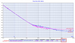
Firstly jitter is not significantly increased by sine to square conversion as clearly showed in the attached plot.
Jitter is practically the same (150fs for the sine wave oscillator vs 160fs for the squarer) and noise floor is almost the same, only 9 dB worse for the squarer and we are talking about -157dBc.
Secondly the the limited input bandwidth of the Timepod (30MHz, the same of the R&S FSWP before the signal was digitized and cross correlation was applied) does not affect the measurement as I have already demonstrated at least two times, but I take note that I will have to do it for the third time.
You still keep forgetting that phase noise means zero crossing so there is no way for the harmonics to alter the measurements unless they affect the zero crossing (phase).
This is curious since you have the skills to understand it.
Attachments
Jitter = Phase Noise. 2 different views of the same thing. The thing being a clock pulse not happening on the theoretically exact point in time - i.e. a timing deviation of a clock.
//
Which means sideband noise in frequency domain.
The only issue is that to accurately measure the jitter you need a tool with a time base phase noise better than the phase noise of the DUT, otherwise you measure the noise floor of the instrument.
Jitter = Phase Noise. 2 different views of the same thing. The thing being a clock pulse not happening on the theoretically exact point in time - i.e. a timing deviation of a clock.
I would not put an equal sign between an integral and an integrand.
At the risk of repeating the obvious:
a) jitter depends fundamentally on the phase noise frequency integration limits. These integration limits were under discussion here, Andrea says that integrating the phase noise from 0.1Hz or 1Hz to 100KHz is universally good enough (for digital audio?), AD in the quoted reference recommends integrating up to the twice the sampling frequency, I was questioning why not integrating from 0.001Hz, if the close in phase noise is all that matters for digital audio.
b) the AD recommendation for the upper frequency integration limit is in particular important for calculating the jitter of non sine signals. Andreas plot already shows a degradation of 9dB in the wideband phase noise floor. While integrating up to 100KHz has indeed a minimum effect on the jitter degradation, integrating according to the AD recommendation would show a much larger jitter degradation.
c) Lo and behold, what do you think is the timepod seeing as coming from a 22MHz input square signal, filtered by the timepod anti-aliasing input filter to some 30MHz? Answer: the fundamental frequency, the same as for the sine before square conversion. While it is well known that the whole sine to square process additive jitter degradation is in the harmonics:
http://people.mpi-inf.mpg.de/~adogan/pubs/IFCS2018_comparator_noise.pdf
https://pdfs.semanticscholar.org/9440/fd4f0e2d65cfed307dfc30892fe9f0bf8c8d.pdf
For the purpose of comparing two arbitrary signals jitters, the model of "zero crossings" is valid only if the bandwidth is infinite. Which, for obvious practical reasons, is not the case here.
What really matters for digital audio, that's a good question I don't have an answer for.
Last edited:
a) this is just the reason why the jitter is useless since the phase noise frequency integration limits are arbitrary, while the phase noise plot shows the whole spectrum of the noise
b) integrating according to the AD recommendation would not change the result since the noise floor point had been reached for both signals (sine and square) and above this point the plot is flat. Moreover you can easily play with a phase noise to jitter converter tool to understand that the higher the distance of the noise from the carrier the lower the calculated jitter is affected.
c) I disagree, just move to a 5MHz fundamental (far above the LPF of the Timepod) and the result does not change, as I have already demonstrated two times. Please take a look at the attached harmonics spectrum of a 5MHz CMOS oscillator. Since the infinite odd harmonics are just the square wave, do you think the even harmonics of the spectrum will affect the jitter? The answer is no as I have demonstrated.
Finally, what really matters for digital audio is a speculation until we don't have an answer for.
I have my opinion while you have a different opinion.
I assume that who has started this thread shares my opinion, otherwise the devices he is selling are really useless.
Attachments

Ian,
at this point I don't understand if your RF skills are very limited or if you are throwing nonsense calculations in order to confuse those who are reading.
I hope the second, otherwise you should restart from scratch.
BTW, assuming the second ipothesys some clarifications are needed.
It's quite curious that now you are pointing to an integration bandwidth from 0.1Hz to 100KHz to calculate the RMS jitter.
I wonder if you understand what this means, I wonder if you understand what tools you need to measure the phase noise so close to the carrier.
I wonder if you know the basis of the cross correlation, I'm not sure.
I'm pretty sure you have not yet understood that when the phase noise has reached the noise floor the plot becomes flat.
At such frequencies like 22/24 MHz the noise floor is reached in the range 1kHz-10kHz so the 100kHz integration bandwidth upper limit is more than enough.
And since you wrote "The phase noise of the BCK is around -140dBc at 10 Hz from the carrier, better than the phase noise of the sine wave input from the Driscoll oscillator at 24.576 MHz. That could be still questioning", I'm sorry to say I have to assume you have not understood how frequency division affects the phase noise.
I would suggest rubiola.org and time-nuts to learn a little.
So, since the jitter is mainly affected by the close in noise, do you think your digital oscilloscope with its poor time base and without cross correlation was able to measure phase noise/jitter at 1 Hz or even 0.1 Hz from the carrier?
The answer is NO, let me explain why.
First picture
The RMS jitter of the DRIXO oscillator at 22.5792 MHz calculated with an integration bandwidth 1Hz to 100kHz is 76fs, no doubt from the upper image.
The RMS jitter of the DRIXO oscillator at 22.5792 MHz calculated with an integration bandwidth 0.1Hz to 100kHz is 980fs (lower image).
It was pretty obvious since the jitter is mainly affected by the close in noise.
Although the jitter noise floor of your digital oscilloscope (2 to 7 ps) is far worse than the DUT you would measure (980fs), there is no way your tool could measure with such integration bandwidth lower limit (0.1 Hz) because its time base is much worse than the DUT and moreover the cross correlation is the only way to reach such lower limit (and your tool does not use cross correlation).
Let me demonstrate the reason.
Second picture
Using an integration bandwidth from 0.1Hz to 100kHz the RMS jitter of the Crystek CCHD-957 is 0.67 ns, while you have measured 2.71 ps with your digital oscilloscope.
This demonstrates that your tool is not able to measure the close in jitter, it substantially measures the noise floor but it's not capable of measuring the close in noise.
It's suitable for telecommunication mesurements but not to measure the close in jitter and it's quite obviuos due to its poor time base.
Third picture
By calculating the RMS jitter of the Crystek CCHD-957 starting from the phase noise plot of its datasheet, the resulting jitter is almost the same measured by the Timepod when using 0.1 Hz to 100 kHz integration bandwidth.
The lower image clearly shows a calculated jitter of 0.47 ns, a little better than the one measured by the Timepod (0.67 ns), maybe the specific DUT has a little worse noise floor.
Anyway the resulting RMS jitter is very similar, 0.67 ns vs 0.47 ns, while you have measured 2.71 ps, more than 2 orders of magnitude better than the real jitter.
I hope it's clear you have no way to measure such close in jitter with your digital oscilloscope, the time base of your tool is much worse than the DUT you would measure.
It's phisically impossible.
Andrea
@andrea_mori
The way of your post doesn’t help to make your point. Actually you mixed up the concepts of time jitter and phase jitter.
Time jitter and phase jitter are totally different things!
For square waves, time jitter describes the uncertainty of the time interval between edges. Time jitter is a real parameter of a clock signal which can be measured directly in the time domain. Time jitter represents exactly the same way how a DAC takes the clock. DACs and streamers don't use sine clocks because the very slow slew rate can result in very high time jitter.
Phase jitter doesn’t exist in the real world. It can just be indirectly calculated from a phase noise plot (of fundamental sine clock in this case). Sometimes people use phase jitter to estimate the time jitter. But it’s just an approach not really equal. Conditions have to be applied. It cannot always be correct, especially at frequencies very close to the carrier. You have to use real measured time jitter as true reference if the calculated phase jitter is different.
A good example is that, the real measured RMS time jitter of CCHD957 22.5792 MHz was less than 3ps. But the phase jitter you calculated was 0.47ns. And your TimePod result was even worse, up to 0.67ns. Unbelievable, your TimePod phase jitter error was 200 times more than the actual RMS time jitter! Everybody can easily confirm that your 0.47ns and 0.67ns phase jitter results are totally wrong by just directly measuring a CCHD957 waveform using any oscilloscope 100MHz or higher.
Ian
Last edited:
Even if it is clear there is some tension in the discussion, I appreciate the technical backgrounds and the positions being taken on both aspects. So thanks for that. It was indeed interesting.
As there is no way to check or even verify any thing myself due to lack of serious test equipment both in time and frequency domain, I am really looking forward to now actually listen to both sine to square converters as that will be the ultimate goal. Is there a difference in perceived sound quality and if so what and how significant.
I have absolutely no bias on the subject just very curious 🙂
Ian,
Jitter and phase noise are the same phenomenon measured in different domains, time and frequency.
The mathematical relationship between the two measurements is precise.
The only issue is that the jitter depends on the ntegration bandwidth, so it changes considerably by varying the integration bandwidth.
And moreover it's mainly affected by the close in noise.
It's a useless arbitrary standalone number because it does not explain anything about the spectrum of the noise.
Why is it arbitrary?
Because if you calculate it converting a phase noise plot the resulting number remarkably changes according to the integration bandwidth you have arbitrarily chosen.
If you directly measure it by a digital oscilloscope the resulting number remarkably changes according to the quality of the tool time base.
In post # 6968 you have arbitrarily chosen an integration bandwidth from 0.1Hz to 100kHz from the carrier to calculate the jitter of the DRIXO oscillator at 24.576 MHz, with the aim of disavowing my measurements.
Let me quote: "”The Driscoll oscillator at 22.5792 MHz has a jitter of 76fs” That’s totally wrong".
Regardless you have pointed to the wrong plot of the 24.576 MHz oscillator (clearly indicated in the graph you have posted) instead of the one at 22.5792 MHz, you used an unfortunate trick to refute the calculated jitter of 76fs, which was calculated with a different integration bandwidth from 1Hz to 100kHz from the carrier.
You have redefined the integration bandwidth from 0.1Hz to 100kHz, so that the calculated jitter was 2.589ps.
The purpose of the trick was to move the calculated jitter of the oscillator above the noise floor of your digital oscilloscope (2 to 7ps), in order to be able to say that you can measure it, while I wrote you cannot measure the added jitter of your SinePi because the jitter of the sine wave oscillator is far lower than the noise floor of your digital scope (almost 2 orders of magnitude, 76fs to at least 2ps).
So that, even if your SinePi will be ferfect adding zero jitter, you would measure a jitter of at least 2ps (the noise floor of your oscilloscope), almost 2 orders of magnitude worse than the jitter of the sine wave oscillator.
The curious thing is that now you are refuting the integration bandwitdh you have previously arbitrarily chosen (0.1Hz to 100kHz from the carrier) to be applied in order to calculate the jitter of the Crystek CCHD-957 I have attached to post #6970.
Let me quote again:
"A good example is that, the real measured RMS time jitter of CCHD957 22.5792 MHz was less than 3ps. But the phase jitter you calculated was 0.47ns. And your TimePod result was even worse, up to 0.67ns. Unbelievable, your TimePod phase jitter error was 200 times more than the actual RMS time jitter!"
It's another trick you are using for the purpose of validating your measurement, because when you have chosen the lower integration bandwidth starting from 0.1Hz from the carrier you have forgot that the poor time base of your digital oscilloscope does not allow to measure such close in noise.
Of course you have ignored the first picture I have posted, where I have clearly explained how the calculated jitter changes as function of the chosen integration bandwidth.
Let me apply the same reasoning to the Crystek CCHD-957 so that it will be clear how you are manipulating the calculations.
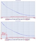
The first plot in the attached picture shows the calculated jitter of the Crystek CCHD-957 with an integration bandwidth from 0.1Hz to 100kHz, just the same you have chosen to calculate the jitter of the DRIXO oscillator.
The resulting jitter is 0.67ns or 670ps, no doubt since I have already posted the calculation using the same online tool you have used to calculate the jitter of the DRIXO oscillator with the same integration bandwidth.
The second plot shows the calculated jitter of the same Crystek CCHD-957 with an integration bandwidth from 1Hz to 100kHz, the close in noise is lost in the calculation.
The resulting jitter is 2.4ps, magically almost the same you have measured with your digital oscilloscope (2.71ps).
What does it means?
It does mean that your digital oscilloscope is not capable to capture the close in noise.
It was quite obvious since your digital oscilloscope has a poor time base and does not use cross correlation, so it cannot capture the close in noise because it's below the noise floor of your tool.
In conclusion, you have no chance to measure the real added jitter by your SinePi, since the jitter of the sine wave oscillator is far below the noise floor of your digital oscilloscope.
This means that you will measure at least a jitter of 2 to 7 ps (the noise floor of your tool) at the output of your SinePi, although it was perfect by adding zero jitter to the incoming sine wave.
Almost 2 orders of magnitude worse than the base oscillator.
And tricks don't help.
Andrea
Jitter and phase noise are the same phenomenon measured in different domains, time and frequency.
The mathematical relationship between the two measurements is precise.
The only issue is that the jitter depends on the ntegration bandwidth, so it changes considerably by varying the integration bandwidth.
And moreover it's mainly affected by the close in noise.
It's a useless arbitrary standalone number because it does not explain anything about the spectrum of the noise.
Why is it arbitrary?
Because if you calculate it converting a phase noise plot the resulting number remarkably changes according to the integration bandwidth you have arbitrarily chosen.
If you directly measure it by a digital oscilloscope the resulting number remarkably changes according to the quality of the tool time base.
In post # 6968 you have arbitrarily chosen an integration bandwidth from 0.1Hz to 100kHz from the carrier to calculate the jitter of the DRIXO oscillator at 24.576 MHz, with the aim of disavowing my measurements.
Let me quote: "”The Driscoll oscillator at 22.5792 MHz has a jitter of 76fs” That’s totally wrong".
Regardless you have pointed to the wrong plot of the 24.576 MHz oscillator (clearly indicated in the graph you have posted) instead of the one at 22.5792 MHz, you used an unfortunate trick to refute the calculated jitter of 76fs, which was calculated with a different integration bandwidth from 1Hz to 100kHz from the carrier.
You have redefined the integration bandwidth from 0.1Hz to 100kHz, so that the calculated jitter was 2.589ps.
The purpose of the trick was to move the calculated jitter of the oscillator above the noise floor of your digital oscilloscope (2 to 7ps), in order to be able to say that you can measure it, while I wrote you cannot measure the added jitter of your SinePi because the jitter of the sine wave oscillator is far lower than the noise floor of your digital scope (almost 2 orders of magnitude, 76fs to at least 2ps).
So that, even if your SinePi will be ferfect adding zero jitter, you would measure a jitter of at least 2ps (the noise floor of your oscilloscope), almost 2 orders of magnitude worse than the jitter of the sine wave oscillator.
The curious thing is that now you are refuting the integration bandwitdh you have previously arbitrarily chosen (0.1Hz to 100kHz from the carrier) to be applied in order to calculate the jitter of the Crystek CCHD-957 I have attached to post #6970.
Let me quote again:
"A good example is that, the real measured RMS time jitter of CCHD957 22.5792 MHz was less than 3ps. But the phase jitter you calculated was 0.47ns. And your TimePod result was even worse, up to 0.67ns. Unbelievable, your TimePod phase jitter error was 200 times more than the actual RMS time jitter!"
It's another trick you are using for the purpose of validating your measurement, because when you have chosen the lower integration bandwidth starting from 0.1Hz from the carrier you have forgot that the poor time base of your digital oscilloscope does not allow to measure such close in noise.
Of course you have ignored the first picture I have posted, where I have clearly explained how the calculated jitter changes as function of the chosen integration bandwidth.
Let me apply the same reasoning to the Crystek CCHD-957 so that it will be clear how you are manipulating the calculations.
The first plot in the attached picture shows the calculated jitter of the Crystek CCHD-957 with an integration bandwidth from 0.1Hz to 100kHz, just the same you have chosen to calculate the jitter of the DRIXO oscillator.
The resulting jitter is 0.67ns or 670ps, no doubt since I have already posted the calculation using the same online tool you have used to calculate the jitter of the DRIXO oscillator with the same integration bandwidth.
The second plot shows the calculated jitter of the same Crystek CCHD-957 with an integration bandwidth from 1Hz to 100kHz, the close in noise is lost in the calculation.
The resulting jitter is 2.4ps, magically almost the same you have measured with your digital oscilloscope (2.71ps).
What does it means?
It does mean that your digital oscilloscope is not capable to capture the close in noise.
It was quite obvious since your digital oscilloscope has a poor time base and does not use cross correlation, so it cannot capture the close in noise because it's below the noise floor of your tool.
In conclusion, you have no chance to measure the real added jitter by your SinePi, since the jitter of the sine wave oscillator is far below the noise floor of your digital oscilloscope.
This means that you will measure at least a jitter of 2 to 7 ps (the noise floor of your tool) at the output of your SinePi, although it was perfect by adding zero jitter to the incoming sine wave.
Almost 2 orders of magnitude worse than the base oscillator.
And tricks don't help.
Andrea
Attachments
That's correct.Jitter and phase noise are the same phenomenon measured in different domains, time and frequency.
Wrong.The mathematical relationship between the two measurements is precise.
The relationship between time jitter and phase jitter is just an approach, not really equal or precise.
My LC584ALX is equipped with a JTA jitter testing package. The jitter noise floor is just 2ps. I attached the JTA specifications for you to reference. Please don’t mislead others with wrong specifications to degrade testing equipment other than yours. Can you explain where the 7ps wrong noise floor number came from?the noise floor of your digital oscilloscope (2 to 7ps)
Crystek CCHD-957 with an integration bandwidth from 0.1Hz to 100kHz, The resulting jitter is 0.67ns or 670ps
CCHD 957 RMS time jitter was tested directly in the time domain of 2.71ps. However the phase jitter calculated by your TimePod was 0.67ns (0.1Hz to 100KHz). By comparison with the time domain measurement, I think your TimePod phase jitter calculation result is inaccurate. If you don’t agree, please show me the evidence of the 0.67ns jitter that you measured a CCHD957 directly in the time domain. 0.67ns jitter is pretty big and can easily be seen even using a normal oscilloscope.
Jitter itself is a time domain concept. Please don’t repeat your TimePod phase jitter result which is what I’m questioning about. You have to approve it.
Ian
Attachments
Apart of the personal issues, the technical merit of the explanation makes sense to me.
Agreed, it's pretty much textbook knowledge, but still doesn't answer to what I would think is a fundamental question: what does matter for digital audio? For a (for example) ADC, "phase noise" is an abstraction, what really matters is the jitter, which creates incertitude in the sampling timing, resulting in digital noise at the output, affecting the ADC SNR.
Jitter can be calculated from the phase noise spectra, but obviously not the other way around: there is no way to reconstruct the phase noise spectra from a single number that is the jitter. But, again from an ADC perspective, does it matter what the original phase noise spectra was? It doesn't, of course.
Secondly, it is true that the close in phase noise may have a significant contribution to the overall jitter (which, once again, it's what ultimately matters). But if we want to estimate an oscillator jitter from a phase noise plot, how can we do that? From the just posted Crystek example, if we integrate from 1Hz we get 2.4pS RMS of jitter, if we integrate from 0.1Hz we get 670pS, so what is the jitter? It appears to depend violently on an arbitrary constant that is the lower limit of integration. Why not integrating from 0.001Hz, since the phase noise will increase fast, then we are going to get an even larger jitter? What is the "true" value of jitter?
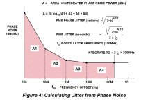
The answer is in the attached chart, from the Analog Devices application note; the relative jitter contribution of the close in phase noise decreases faster than the phase noise increase per the Leeson model. So there is a frequency point from which the close in phase noise contribution to the jitter becomes insignificant. Where is that point, that is a good question; so from a jitter perspective, the phase noise profile is much more relevant than ultra low phase noise values at 0.1Hz.
There is another thing here: the close in phase noise affects the spectral resolution of the system output, while the broadband noise (the "flat" part) affects the ADC SNR. One has to answer the question of what matters most for digital audio, something we have nothing but anecdote level evidence about, stories from usually self appointed Golden Ears uncontrolled, sighted listening tests. Based only on the current body of evidence, I would think SNR is the right metric (which does not mean we can hear a difference between 110dB and 120dB of SNR). Except, of course, for specialty applications like radars or space guidance systems, where the spectral resolution is of course critical.
Attachments
- Home
- Source & Line
- Digital Line Level
- Asynchronous I2S FIFO project, an ultimate weapon to fight the jitter