
I changed the input to a jfet, this is to take away the need for input cap.
Hawksford IPS cascode, listening tests has proven more warm slam with the Hawksford cascode.
bootstrap VAS, drive the Lat-fets directly.
I,ts also possible to insert a mirror over the VAS transistor, This will increase open loop gain and improve the distortion, but I really see no gain as it already does something like 10 ppm
HI MIIB, and what is this cascode ?
https://sites.google.com/site/franc...teur/6-4-l-amplificateur-digora/Digora_v3.gif
The Leds are not referenced to ground but to the source of the Fet.
That is a driven cacode that also could be called Hawksford cascode although in Hawksfords paper it is the VAS where he used that trick.
Further research sugests that this was known before Hawksford but the name stuck.
That is a driven cacode that also could be called Hawksford cascode although in Hawksfords paper it is the VAS where he used that trick.
Further research sugests that this was known before Hawksford but the name stuck.
There is a clear benefit of having a low AC resistance in the bias spreader, this is the reason for the capacitance over the resistor
The removal of the VBE is due to the fact that LAT fest does not really need them, but still some do recommend VBE, just to be on the safe side.
The removal of the VBE is due to the fact that LAT fest does not really need them, but still some do recommend VBE, just to be on the safe side.
Member
Joined 2009
Paid Member
Well, bootstraps are quite simple but they depend heavily on the used caps..... can we not use two CCS one on each rail side ?
Yes to both. And you might like to take a different path. There are many many options - the main thing is that this is your amplifier, you get to choose what goes in and how it works 🙂
Joachim, I like to use driven cascode on the VAS to, but I really did not want to take this too far,
The input Fet really needs shielding from the Rail-voltage, this is why i use the cascode.
True this circuit does away with the mirrors for the bias spreader, in realty there's a thousand ways of doing the spread, resistors diodes, all sound different and is clearly an area to explore.
There are more ways to adjust the offset, It can also be done by adjusting the value of resistor R1 here 135 ohms gives app 0.offset (this affect the Open loop gain as well) but still it does less than 20 ppm with a good distribution
Last edited:
Yes to both. And you might like to take a different path. There are many many options - the main thing is that this is your amplifier, you get to choose what goes in and how it works 🙂
Will study two ccs tonight..... Thank you Gareth
Joachim, I like to use driven cascode on the VAS to, but I really did not want to take this too far,
The input Fet really needs shielding from the Rail-voltage, this is why i use the cascode.
True this circuit does away with the mirrors for the bias spreader, in realty there's a thousand ways of doing the spread, resistors diodes, all sound different and is clearly an area to explore.
There are more ways to adjust the offset, It can also be done by adjusting the value of resistor R1 here 135 ohms gives app 0.offset (this affect the Open loop gain as well) but still it does less than 20 ppm with a good distribution
This one will be my third amp 🙂
Thank you Miib.
I changed the input to a jfet, this is to take away the need for input cap.
Hawksford IPS cascode, listening tests has proven more warm slam with the Hawksford cascode.
bootstrap VAS, drive the Lat-fets directly.
I,ts also possible to insert a mirror over the VAS transistor, This will increase open loop gain and improve the distortion, but I really see no gain as it already does something like 10 ppm
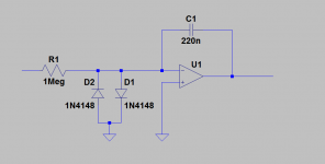
Michael, I have in the past made some experiences with two poles DC servos and come to the conclusion that the simple 1 pole dc servo is the fastest and better, adding more than 1 pole make the servo to slow, the output voltage swings for some time before it reach zero volts at output, adding a third pole will make the servo unstable and will oscillate at very low frequencies, Also in the past I use 2u2 and 1u in the dcservo but that was also to slow, especially with vinyl, it was visible the exaggerated low frequency movements in the speakers, Joachim recommended that I use smaller capacitors in that position, and now I use 100n or 220n.
I think that the bad reputation of the DC servo is due to the slow speed, and in the past I also try to stay away from servos, but not anymore 🙂 thanks to Joachim . I normally use a opa134 and this simple circuit.
Attachments
We are working on the sub saturation range. The models are not perfect yet.
Nice, If you guys are in the mood to share, that will be useful. Better spice models are in need, the best lateral mosfet models that I find until now are from Cordell.
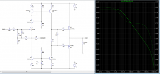
A simple circuit following the spirit of the thread 🙂.
it needs a DC servo. there is no need for miller compensation because the parasitic capacitances of the output mosfet will be enough to compensate the open loop.
with some modifications a nice headphone amplifier could be made.
it needs a DC servo. there is no need for miller compensation because the parasitic capacitances of the output mosfet will be enough to compensate the open loop.
with some modifications a nice headphone amplifier could be made.
Attachments
Sergio the master of simplicity.....🙂
This leads me to The Circle
Why not assemble everything into the floating current source. then mirror directly over into the bias spreader, All is in a circle, what goes in must come out.
Here is the input Jfet is close to ideal, as it's the best V/I converter we have.
This leads me to The Circle
Why not assemble everything into the floating current source. then mirror directly over into the bias spreader, All is in a circle, what goes in must come out.
Here is the input Jfet is close to ideal, as it's the best V/I converter we have.
Attachments

Last edited:
there is no need for miller compensation because the parasitic capacitances of the output mosfet will be enough to compensate the open loop.
Is this true for the other lateral schematics we have here ?
you can choose where to make your compensation, miller or use the LAT capacitance with high(ish) gate stoppers, take your poison..🙂
Sergio the master of simplicity.....🙂
This leads me to The Circle
Why not assemble everything into the floating current source. then mirror directly over into the bias spreader, All is in a circle, what goes in must come out.
Here is the input Jfet is close to ideal, as it's the best V/I converter we have.
In this case, the VAS is inside the mirror right ?
If I wanted to add miller could I do it in the KSA trannie ?
PS: Beware the blue leds..... noisy stuff.... IMO the best are ambar
- Home
- Amplifiers
- Solid State
- Assemblage Power Amp