I just put the blue there to get the voltage, amber or red are what i normally use.
Jfet does the amplification and V/I conversion, the mirror scales the current that then pulls the spreader up and down (here a hawks-ford cascode would be good) the LAT's then transforms into a low impedance voltage out.
there are more ways to compensate, the obvious would be a small (22p-47p) capacitor directly from one side of the bias spreader to the feedback node.
Last edited:
As you can see the P-Channel is trouble.
I checked another P-Channel that looked the same.
I hope i do not have fakes.
I have those Fets since a relative long time and they look genuin.
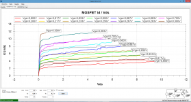
I breafly measured the Exicons and they look much better.
I publish that in the next halve hour.
I checked another P-Channel that looked the same.
I hope i do not have fakes.
I have those Fets since a relative long time and they look genuin.
I breafly measured the Exicons and they look much better.
I publish that in the next halve hour.
Attachments
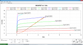
I do not fully understand the readings
Look at the yellow and dark green lines in the first graph ...
Look at the yellow and dark green lines in the first graph ...
Yellow, dark is the P-channel.
The readings shows that it is not a particular good CCS under 6V Vds.
You could also say it has a low early voltage although the phenomenon that causes this is not the same then in BJTs where this term is used.
The readings shows that it is not a particular good CCS under 6V Vds.
You could also say it has a low early voltage although the phenomenon that causes this is not the same then in BJTs where this term is used.
Michael, I have in the past made some experiences with two poles DC servos and come to the conclusion that the simple 1 pole dc servo is the fastest and better, adding more than 1 pole make the servo to slow, the output voltage swings for some time before it reach zero volts at output, adding a third pole will make the servo unstable and will oscillate at very low frequencies, Also in the past I use 2u2 and 1u in the dcservo but that was also to slow, especially with vinyl, it was visible the exaggerated low frequency movements in the speakers, Joachim recommended that I use smaller capacitors in that position, and now I use 100n or 220n.
I think that the bad reputation of the DC servo is due to the slow speed, and in the past I also try to stay away from servos, but not anymore 🙂 thanks to Joachim . I normally use a opa134 and this simple circuit.
There two contradictory requirements for a DC servo, to have short settle time and low corner frequency. If you use to high corner frequency then low frequency distortion rises, so you need a compromise here.
Regarding a vinyl it is other reason for the low frequency movements in the speaker, mostly rumble from the TT motor. To prevent it use HP filter at the amp input.
I am trying to solve that contradictory DC servo requirements, look this DC servo idea here. http://www.diyaudio.com/forums/solid-state/243481-200w-mosfet-cfa-amp-55.html#post4091064.
If I replace 2.2 u caps with 470n it is still working good and increase in low frequency distortion is much lower the if DC servo connected traditionally to the NFB input.
Comments are welcome and improvement suggestion too.
Damir
Jfet does the amplification and V/I conversion, the mirror scales the current that then pulls the spreader up and down (here a hawks-ford cascode would be good) the LAT's then transforms into a low impedance voltage out.
there are more ways to compensate, the obvious would be a small (22p-47p) capacitor directly from one side of the bias spreader to the feedback node.
Where would you place the cascode ? inside the mirror ?

Finished the KSA mod.
Everything looks normal with the reduced miller cap (22p) into a 7ohm load.
Let us see if it is stable with the speakers.....
Everything looks normal with the reduced miller cap (22p) into a 7ohm load.
Let us see if it is stable with the speakers.....
Member
Joined 2009
Paid Member
It's been around 15 minutes now - hope that means it sounds so nice you can't tear yourself away 🙂
Well, I have been dining with my wife while the contraption was left "burning in" with some resistive load...... finally got back into the "lab" and finetuned the offset... and here we go....
1st impression.... aggressiveness lost.... larger soundstage.... must wait until the cart heats up.
Quite pleased I am 🙂
1st impression.... aggressiveness lost.... larger soundstage.... must wait until the cart heats up.
Quite pleased I am 🙂
Hi have a test disc..... Ralph Towner's City of Eyes.... it is a splendid acoustic recording with loads of bells, flutes guitars ... all touched in a manner that can only be heard if the system is "right"..... I am now getting some pleasure out of it...
Will switch to the main system during weekend so a better subjective impression might be posted.
It seems the magic is in the VAS after all 🙂
Will switch to the main system during weekend so a better subjective impression might be posted.
It seems the magic is in the VAS after all 🙂
After some time listening to the assemblage amp on my main system I am sure these last mods went in the good direction.
Lost is the harshness in the treble that now is acceptably extended. The amp sounds fast and not fatiguing.
What I sense now is some lack of control in the ever present bass that somehow sounds slightly monotonic.
I guess reducing the miller cap increased slew rate (and that is clear due to the better highs) but also reduced local feedback in the vas reducing it's linearity.
In the near future I will increase the cap to gnd on the NFD node but I am also considering the implementation of the emitter follower in the miller loop (TGM8).
After all the schematics posted here I still do not understand why I should not use a mirror to drive the output stage.... IMO it seemed a good idea because it renders the driving circuit rather symmetrical and somehow isolates output stage from the VAS.
I now know the crucial importance of the VAS in the power amp. It should provide the highest slew rate without compromising stability and it is there we can determine the overall "tone" of the amp.
LTP reduces 2nd so uneven harmonics dominate and that is why I preferred the singleton.
Now Miib posted a k170 input cascaded that should sound really good.
It will be my next amp.
I changed the input to a jfet, this is to take away the need for input cap.
Hawksford IPS cascode, listening tests has proven more warm slam with the Hawksford cascode.
bootstrap VAS, drive the Lat-fets directly.
I,ts also possible to insert a mirror over the VAS transistor, This will increase open loop gain and improve the distortion, but I really see no gain as it already does something like 10 ppm
This one looks very good to me.
The single resistor spreader should sound much more linear than a vbe multiplier.
The cascoded k170 might provide wider bandwidth...... just not sure it can drive the miller cap without compression.
Last edited:
A simple circuit following the spirit of the thread 🙂.
it needs a DC servo. there is no need for miller compensation because the parasitic capacitances of the output mosfet will be enough to compensate the open loop.
with some modifications a nice headphone amplifier could be made.
Sergio the master of simplicity.....🙂
This leads me to The Circle
Why not assemble everything into the floating current source. then mirror directly over into the bias spreader, All is in a circle, what goes in must come out.
Here is the input Jfet is close to ideal, as it's the best V/I converter we have.
Following this thread's tendencies as Sergio said, we have these two options.
I wish I could really understand the benefits of the mirror in order to be able to choose the most promising schematic
The mirror was taken over from the Nobrainer, a rather simple design that works but does not have any aspiration to be particular good.
I used the mirror because it works.
That is maybe an unsatifying explanation but it is what it is.
Then the mirror was improved twice, first by Frans and then by Michael.
The design has mutated so much that i can understand why the mirror is questioned now.
When you really want tight bass you need more feedback.
Under this premiss it may be a good idea to use a different VAS, even without the mirror when that gives more open loop gain.
The Circle has more than 70 dB open-loop gain.
Extremely good distortion distribution and the absolute beauty of Pass simplicity.
It's really a summation of this thread, Sergio's eye for simplicity and Gerhard's widespread use of mirrors. To be Honest I am quite stunned with the results it produces, and I really like the fact that everything is in a circle. Only issue is the different gender-HFE's of the mirror transistors, this produces a little offset. A servo may be needed due the thermals. it's possible that it will be sufficient to adjust the offset by trimming one of the mirror transistors.
Last edited:
- Home
- Amplifiers
- Solid State
- Assemblage Power Amp