When I was in school, my friend and I used to visit music stores to purchase cassettes or record songs from LPs.
When we heard music from the deck set, we were ecstatic. and we assumed that only wealthy people could use that equipment.
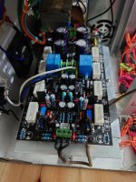
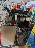
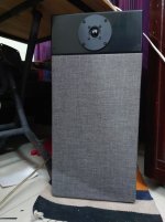
When I was a college student in the 1990s, I took the initiative to build a Hi-Fi! I was told by my other friend that there is a man in Pabna City (150Km away from my home) who makes these kinds of chassis, so I went to his house to build the amp chassis, and I made it.
I moved away from home in 1999 to pursue a job and further my education in Dhaka (Capital of Bangladesh),
and as time went on, the sound system developed rust and dust accumulation, leading to malfunctions! Twenty years later,
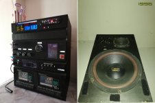
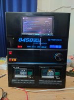
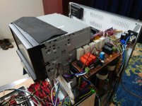
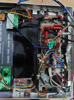
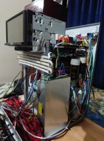
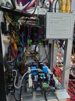
I decided to update the system. Last August, I transported the system from Rajshahi (My home Town) to Dhaka by courier service;
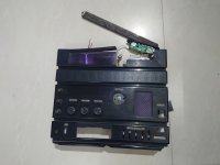
they broke the front panel. then I have taken a different approach, and this is it.
The cassette player is broken. I only keep it as a reminder of the 90s.
When we heard music from the deck set, we were ecstatic. and we assumed that only wealthy people could use that equipment.
When I was a college student in the 1990s, I took the initiative to build a Hi-Fi! I was told by my other friend that there is a man in Pabna City (150Km away from my home) who makes these kinds of chassis, so I went to his house to build the amp chassis, and I made it.
I moved away from home in 1999 to pursue a job and further my education in Dhaka (Capital of Bangladesh),
and as time went on, the sound system developed rust and dust accumulation, leading to malfunctions! Twenty years later,
I decided to update the system. Last August, I transported the system from Rajshahi (My home Town) to Dhaka by courier service;
they broke the front panel. then I have taken a different approach, and this is it.
The cassette player is broken. I only keep it as a reminder of the 90s.
Attachments
-
 set_01.jpg423.3 KB · Views: 97
 -
 set_02.jpg298.6 KB · Views: 92
 -
 set_03.jpg367.2 KB · Views: 97
 -
 set_04.jpg430.4 KB · Views: 100
 -
 set_05.jpg387.9 KB · Views: 90
 -
 set_06.jpg460.5 KB · Views: 101
 -
 set_07.jpg380 KB · Views: 95
 -
 set_08.jpg441 KB · Views: 91
 -
 set_09.jpg409.7 KB · Views: 90
 -
 set_10.jpg413.6 KB · Views: 99
 -
 set_11.jpg401.9 KB · Views: 90
 -
 set_12.jpg409.1 KB · Views: 94
 -
 set_13.jpg420.3 KB · Views: 87
 -
 set_14.jpg350.3 KB · Views: 93
This person inspires me, and I admire him. He is prosperous; I am notOh, sorry, I am in part responsible , at least for the car related bit.
I compared copypasting random circuit bits to assembling wild cars out of completely unrelated parts.
Lo and behold, there is such a guy, Leepu, successfully assembling wild cars using that method.
View attachment 1318672
He hosts a successful "reality" TV show in none less than History Channel.
Even funnier, he is Bangladeshi like Mr Opusadat 😱
Proof of "small world", "reality beats fiction" and so on 😀
Clearly a gifted Mechanic.
To see other cars he made:

@JMFahey You may say that, because Legends born there. you will find more than 100 million Argentinean Fan in Bangladesh!! Last February, your foreign minister (Santiago Andres Cafiero) Visited Bangladesh and He had made the announcement of opening the embassy in bd. that will great opportunity for us to visit Argentina!
It would be impolite to leave a question without an answer.Why do you think like that? When we discuss something, some unrelated matter comes up, but that does not mean we are out of the topic.
Simple answer is that being out of the topic does not bother me, the main problem is that the structure of your text reminds me of the output of ChatGPT.
And that I do not like so I am out of here.
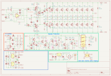
Hi everyone, I have changed the entire audio stage and replaced it with an op-amp [NE5534] and removed all base stopper resistors. I guess that will help to reduce PCB layout complexity. and I have not to bother for the DC offset. What is your opinion about that? Will it work?
**Off Topic:
I guess @madis64 is a little bit disappointed in me! Actually, I do a government job so that every day I send mail to government high officials like the Ministry and other government wings. Every mail is very formal. In our government system, we do paperwork in our native language (Bangla). But we can communicate over mail in English (preferably in our native language). and I am an expert on mistyping and spells mistakes and grammatical errors as well. I have installed "QuillBot." plugings It's quite helpful, this is the reason it looks like AI!!! I type everything, and I have never used ChatGPT.
Attachments

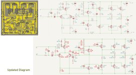
That looks like the old BGW circuit, with a 5534 instead of the old LM318. Base to supply resistors on Q7 and Q8 are missing. VAS will go into limit. Compensation will need to be played with (C22 lead capacitor is too large and it will oscillate).
C14 and 15 are a risk item. When initially uncharged, they will cause high current in the VAS during turn on, and with it excessive bias in the output stage. The old hometaxial 2N6259’s used in the original design could take it. Not sure the modern ones will Indefinitely. And when you do it this way, you need to swap the + and - inputs on the op amp because of the phase reversal. Eventually even BGW added the normal level shift stage which eliminates both issues.
The small signal part of the circuitry is not the problem as far as PCB complexity goes.
ok... then I will replace 2705/1145 pair(s) with bd139/bd140 or MJE340/350 that will be more simple. inv.input will be Input and noninv.inupt will be feedback right?
thanks 🙂
thanks 🙂
Sigh ... You really need to study the basics.
The input stage for the 5534 is messed up.
For the output stage, as the maximum output swing of 5534 is +/-13V (typ.) on +/-15V rail, one pair of 200W transistors would be enough to drive a 4 or 8 ohm speakers. No need for +/-70V rail nor 8 pairs of 200W transistors. Actually, you would want to avoid using +/-70V, as the timing of the turn on/off sequence of the +/-70V rails and +/-15V rails would be critical not to fry 5534.
It's not easy for opamps to drive uF range of capacitance. You will most likely need a series resistance at the output of 5534.
The values of the resistors for the input and feedback loop are too high for 5534 for the best S/N. Pick a JFET input opamp if you want to keep those values.
The gain is too high, as the maximum input voltage would be 0.15Vrms, that's kind a low.
There are many good designs for the Opamp + Output stage configuration on this forum. My sincere advice is to start by copying of one of them. One recent impressive example is:
https://www.diyaudio.com/community/...te-low-power-class-a-amplifier-my-way.404147/
Best,
Satoru
The "gain control" by opto isolator looks super sketchy to me. I haven't analyzed the circuit in detail, so it's possible that I'm missing something, but it looks to me like you're planning to drastically reduce the gain of the amp when the amp is clipping. Are you confident that the amp will be stable at both the nominal gain and at the "clipping gain"? How much performance are you leaving on the table with this feature?
An easy way to turn this from a very expensive project and big boom on startup is to only populate one pair of output devices (Q32, Q33). Put a 10 Ω, 0.25 W resistor in series with each high-voltage rail. Often the resistors will smoke if the amplifier misbehaves.
Tom
An easy way to turn this from a very expensive project and big boom on startup is to only populate one pair of output devices (Q32, Q33). Put a 10 Ω, 0.25 W resistor in series with each high-voltage rail. Often the resistors will smoke if the amplifier misbehaves.
Tom
Safer way to do the clip limiting is simply to attenuate the input signal upon loss of feedback. An LED/LDR type optocoupler is often used, as it introduces a minimum of distortion. An OTA can be used as a variable resistor, also in shunt with the input to do similar attenuation. Faster response, only a little more distortion, but unfortunately higher noise.
Populating only one output pair initially, and driving 20 to 30 ohms is the proper way to test any amplifier like this - new design, new build with proven design, or repair. Get the bugs out first. It’s a good use for the oddball transistors that don’t match. You are going to want to do at least crude matching of the parallel outputs if you want any sort of reliability. To get the best SOUND you want 3 mV Vbe match and 10% on hFE, at operating current. And between NPN and PNP banks, if you can swing it.
Populating only one output pair initially, and driving 20 to 30 ohms is the proper way to test any amplifier like this - new design, new build with proven design, or repair. Get the bugs out first. It’s a good use for the oddball transistors that don’t match. You are going to want to do at least crude matching of the parallel outputs if you want any sort of reliability. To get the best SOUND you want 3 mV Vbe match and 10% on hFE, at operating current. And between NPN and PNP banks, if you can swing it.
now I am your subscriber! 🙂The "gain control" by opto isolator looks super sketchy to me. I haven't analyzed the circuit in detail, so it's possible that I'm missing something, but it looks to me like you're planning to drastically reduce the gain of the amp when the amp is clipping. Are you confident that the amp will be stable at both the nominal gain and at the "clipping gain"? How much performance are you leaving on the table with this feature?
An easy way to turn this from a very expensive project and big boom on startup is to only populate one pair of output devices (Q32, Q33). Put a 10 Ω, 0.25 W resistor in series with each high-voltage rail. Often the resistors will smoke if the amplifier misbehaves.
Tom
Hi opusadat,Last night I caught by fever... but I got more fever when I read the feedback. Now I understand how empty I am!! I need to restart everything, and before that, I need to study more.
Thanks a lot for your inputs, Time to time I will update my status
You are not empty. You are filled with the motivation and willingness to build your first amplifier. You just need to learn about amplifiers here and there. Everybody started from zero knowledge and you are no exception. Some started by reading books and some jumped in by building something before reading about theories. I hope you will enjoy every steps of learning electronics and amplifier design and building as a hobby since it can be very rewarding.
Best,
Satoru
First, it helps to set the goal. Your first post is not clear.
Are you building 1000 watts PA amplifier? Number of outputs suggests that.
If PA, why not classD?
If not PA, do you really need 1000 watts?
Do you care about power or quality?
Wouldn't it make more sense first build kit? Have satisfaction from successful build?
If you however, want to design your own amplifiers, shouldn't you first read some books? Gather some theoretical knowledge? You either get knowledge by building, or by studying. Or both.
If you want to design your own circuit, copy- paste is not the best way. Simulation software is better approach. Designing 3-5 watt amplifiers first, before ten pairs of outputs on +/_70 volts is way to go. The way you are starting is not going to work, sorry.
Your kind feedback is meant a lot to me. Thank you.Hi opusadat,
You are not empty. You are filled with the motivation and willingness to build your first amplifier. You just need to learn about amplifiers here and there. Everybody started from zero knowledge and you are no exception. Some started by reading books and some jumped in by building something before reading about theories. I hope you will enjoy every steps of learning electronics and amplifier design and building as a hobby since it can be very rewarding.
Best,
Satoru
@adason
Thanks. You have caught my intention.
** Yes, I am trying to make a PA.
** Power is an important issue. The PA can handle a 15-inch passive 2-way speaker system.
** Due to component availability in our local market, Class D will be quite challenging to build. almost 0% chances
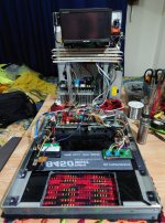
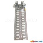
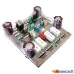
Now the question is, why am I taking this step to build a PA?!! There is blank space in the market to locally produce entry level PA; that can perform a 50–100-person event or indoor program. The market will accept me or not; that does not matter. The matter is that I'm trying to build a PA that can comply with at least 80% of the standard parameters. locally designed or copied PCBs are junk. How they got those circuit diagrams and who gave it to them, only God knows. I have attached some locally made PCB.
I hope you get my point. and I'm guessing you are quite a bit confused!! Actually, it's quite hard for you to assume that how third-world countries like Bangladesh run. Our social and economic parameters are different, which reflects on our work. though we are trying to overcome this.
Thanks
opu
Thanks. You have caught my intention.
** Yes, I am trying to make a PA.
** Power is an important issue. The PA can handle a 15-inch passive 2-way speaker system.
** Due to component availability in our local market, Class D will be quite challenging to build. almost 0% chances
Now the question is, why am I taking this step to build a PA?!! There is blank space in the market to locally produce entry level PA; that can perform a 50–100-person event or indoor program. The market will accept me or not; that does not matter. The matter is that I'm trying to build a PA that can comply with at least 80% of the standard parameters. locally designed or copied PCBs are junk. How they got those circuit diagrams and who gave it to them, only God knows. I have attached some locally made PCB.
I hope you get my point. and I'm guessing you are quite a bit confused!! Actually, it's quite hard for you to assume that how third-world countries like Bangladesh run. Our social and economic parameters are different, which reflects on our work. though we are trying to overcome this.
Thanks
opu
Attachments
- Home
- Amplifiers
- Solid State
- As I create my first amplifier diagram, I eagerly await your feedback