Amplifiers with that many power transistors are not easy to make PCBs for. Making everything align properly on the heat sink and fit into the chassis will make you go through multiple “generations” before everything FITS TOGETHER properly enough to actually be able to build it. Unless you’re going to get all those parts custom manufactured and machined from CAD drawings. And pay thousands of dollars to get it done.
Then it has to work electrically, as you intended it to. Following Selfs 11 cardinal rules concerning EM compatibility get exponentially harder with each pair you add.
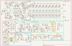
It has to be designed together, electrically, mechanically and thermally as a system. Physical construction needs to be worked out, long before a schematic is finalized. I don’t see anything “wrong” with the design, and other than some minor optimization, will WORK, and work safely/reliably if the physical construction is up to snuff.
Then it has to work electrically, as you intended it to. Following Selfs 11 cardinal rules concerning EM compatibility get exponentially harder with each pair you add.
It has to be designed together, electrically, mechanically and thermally as a system. Physical construction needs to be worked out, long before a schematic is finalized. I don’t see anything “wrong” with the design, and other than some minor optimization, will WORK, and work safely/reliably if the physical construction is up to snuff.

R52 and R53 I would move to 1 ohm
These are driver / outputs you may overload them before the others kick in .
The design here lends itself to 4 1n4148's as the VAS bias circuit with 1 ohm driver resistors.
Your preamp won't pass any signal the first 5532 has no resistor in its feedback 2 *27k would work. Your volume pot is in wrong spot. Reverse position with 10k feedback resistor.
220 ohm amp feedback to 1k.
Last edited:
R25, R26, D11, and D12 are in the wrong place. See Leach's schematic.
The abundance of 100 ohm resistors tells me that the designer did not know how to calculate the values, or whether the resistor was necessary. The amplifier probably works, but not very well.
This board has quite a few well-designed amplifiers that you can build.
Ed
The abundance of 100 ohm resistors tells me that the designer did not know how to calculate the values, or whether the resistor was necessary. The amplifier probably works, but not very well.
This board has quite a few well-designed amplifiers that you can build.
Ed
Transistors 2SD669, 2SC5171, 2SA1930, 2SC4793, 2SA1837, 2SC2705, 2SA1145 are all obsolete and hard to obtain. I strongly advise not to use any of those you can buy on eBay or Aliexpress. Those are all fake. There may be some that are genuine, but the chance of getting them is slim. In the place of 2SC5171/2SA1930, you can use TTC011B/TTA006B pair. Others may have suggestions for the substitute for 2SC2705/2SA1145 pair.
MJL21193G and MJL21194G have limited fT at 4MHz. Why not use 2SC5200/2SA1941 (or current models, TTC5200/TTA1941) instead since you are already using them?
By using lateral MOSFET (like ECW20P20 / ECW20N20 pair from Exicon, 200V, 16A, 250W parts), you can worry less about the thermal management of the output stage. Since this is your first project, you may want to reduce some issues that are dependent on execution of the design, like where and how to mount the transistors for the thermal compenstation of the output stage.
I would make the input stage transistors cascoded at this voltage.
As others have mentioned, you may want to consider the value and neccesities of some 100 ohm resistors. Some are not required and some should be in different values.
Good luck and enjoy your first build!
Satoru
I much appreciate your warm comments.Amplifiers with that many power transistors are not easy to make PCBs for. Making everything align properly on the heat sink and fit into the chassis will make you go through multiple “generations” before everything FITS TOGETHER properly enough to actually be able to build it. Unless you’re going to get all those parts custom manufactured and machined from CAD drawings. And pay thousands of dollars to get it done.
Then it has to work electrically, as you intended it to. Following Selfs 11 cardinal rules concerning EM compatibility get exponentially harder with each pair you add.
It has to be designed together, electrically, mechanically and thermally as a system. Physical construction needs to be worked out, long before a schematic is finalized. I don’t see anything “wrong” with the design, and other than some minor optimization, will WORK, and work safely/reliably if the physical construction is up to snuff.
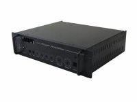
Localy made an amplifire chassis (50 cm x 20 cm x 8 cm) will cost you between $12 and $15. I've included a picture of the chassis.
They will build the chassis to my specifications if I pay extra. Additionally, heat sinks are accessible, and I was able to get one that will enable me to create the PCB the correct size.
Attachments
point acknowledged; I'll share it once again after revisions. I much appreciate your warm comments.R52 and R53 I would move to 1 ohm
These are driver / outputs you may overload them before the others kick in .
The design here lends itself to 4 1n4148's as the VAS bias circuit with 1 ohm driver resistors.
Your preamp won't pass any signal the first 5532 has no resistor in its feedback 2 *27k would work. Your volume pot is in wrong spot. Reverse position with 10k feedback resistor.
220 ohm amp feedback to 1k.
point acknowledged; I'll share it once again after revisions. I much appreciate your warm comments.R25, R26, D11, and D12 are in the wrong place. See Leach's schematic.
The abundance of 100 ohm resistors tells me that the designer did not know how to calculate the values, or whether the resistor was necessary. The amplifier probably works, but not very well.
This board has quite a few well-designed amplifiers that you can build.
Ed
@satour, I appreciate your feedback. You are 100% correct on transistors. I'll take your recommendations into account. The MJW3281A/MJW1302A power transistor (copy-paste issue) will be used. I've made a list of several transistors, and I'll include your suggested transistor as well.
Driver Transistors
Power Transistor
Driver Transistors
| NPN | PNP | hFE min | Pd | Vcb/Vce | Ic | Hz | pF |
| LTP/200MHz | |||||||
| 2N5551 | 2N5401 | 80 | 0.31W | 180V | 0.6A | 100 MHz | |
| Pre-Driver/150MHz | |||||||
| 2N5551 | 2N5401 | 80 | 0.31W | 180V | 0.6A | 100 MHz | 6 |
| C2240 | A970 | 200 | 0.3W | 120V | 0.1A | 50 MHz | 3 |
| A92 | A42 | 70 | 0.055W | 18V | 0.005A | 20 MHz | |
| VAS/Bias/100MHz | |||||||
| C2705 | A1145 | 80 | 0.8W | 150V | 0.05A | 200 MHz | 1.8 |
| 2SC3423 | 2SC1360 | 70 | 5W | 150V | 0.05A | 200 MHz | 2.5 |
| D669 | B649 | 60 | 1W | 120V | 1.5A | 140MHz | 14 |
| MJE340 | MJE350 | 30 | 20W | 300V | 0.5A | 10 MHz | |
| BD139 | BD140 | 40 | 12W | 80V | 1A | 50 MHz | |
| Driver 1st/30MHz | |||||||
| TIP 31C | TIP 32C | 20 | 40W | 140V | 3A | 3 MHz | |
| TIP 41C | TIP 42C | 20 | 65W | 140V | 6A | 3 MHz | |
| C4793 | A1837 | 100 | 50W | 230V | 1A | 100 MHz | 20 |
| 2SC5171 | 2SA1930 | 100 | 20W | 180V | 2A | 200 MHz | 26 |
| MJE15032 MJE15034 MJE15028 MJE15030 | MJE15033 MJE15035 MJE15029 MJE15031 | 50 | 50W | 250V 350V 120V 120V | 8A | 30 MHz | |
| C2073 | A940 | 40 | 25W | 150V | 1.5A | 1MHz | 70 |
| Driver 2nd/30MHz | |||||||
| C5198 | 1941 | 55 | 100W | 160V | 10A | 30 MHz | 220 |
Power Transistor
| NPN | PNP | hFE | hFE | Pd | Vcb/Vce | Ic | Hz | pF | Brand |
| TTC5200 | TTL1943 | 80-160 | 150W | 230V | 15A | 30 MHz | 145 | Toshiba | |
| 2SC5200 | 2SA1943 | 55-160 | 150W | 250V | 15A | 30 MHz | 200 | Toshiba | |
| 2SC5949 | 2SA2121 | 55-160 | 220W | 200V | 15A | 30 MHz | 270 | Toshiba | |
| 2SC5198 | 2SA1941 | 55-160 | 100W | 160V | 10A | 30 MHz | 320 | Toshiba | |
| MJW3281A | MJW1302A | 50-125 | 200W | 230V | 15A | 30 MHz | 600 | ON Semi | |
| NJW0281G | NJW0302G | 86/79 | 75-150 | 150W | 250V | 15A | 30 MHz | 400 | ON Semi |
| MJL21194 | MJL21193 | 43/78 | 25-75 | 200W | 400V | 16A | 4 MHz | 500 | ON Semi |
| NJL3281D | NJL1302D | 75-150 | 200W | 260V | 15A | 30 MHz | 600 | ON Semi | |
| MJL4281A | MJL4302A | 80-250 | 230W | 350V | 15A | 35 MHz | 600 | ON Semi |
There is nothing wrong with 4 MHz output transistors if you are using them in a triple EF with sustained beta high fT parts in both of the other positions. It will likely give you less trouble with stability with that many spread out all over the place. Fast parts don’t like long distributed buses with lots of inductance that you cannot remove. Keep the base stoppers on the outputs, but drop them to 1 or 2 Ohms. You need something, but not much. Bump the Rbe to between 5 and 20 ohms to increase the current in the C5200 (or C5242, Fairchild’s easier to find version of C5198) drivers. That will also improve switch off time in the 4 MHz outputs.
Hi there, The schematic could not be completed without your help. Many thanks.
I attempted to include your suggestions into the diagram (Attachment).
I think the Q13/15 & Q14/16 are a darlington pair. Should I keep these two or swap them out for 2SC517 & 2SA1930?
Thanks.
opu
I attempted to include your suggestions into the diagram (Attachment).
I think the Q13/15 & Q14/16 are a darlington pair. Should I keep these two or swap them out for 2SC517 & 2SA1930?
Thanks.
opu
Attachments
Last edited:
I use discrete darlingtons in VAS. With the first collector tied to ground and with Rbe set to force about 2 mA in the first transistor. If you do that you can use beefy second transistors and not worry about a 25 or 30 pF Cob ruining things.
With due respect, that is not design but a mishmash of bits and pieces copypasted from all over the world.
I can not kludge together a Ferrari transmission, a Trabant chassis, 4 various sized wheels, a carburetor, a Diesel engine, and say: "hey, look at the car I designed", even if all those are car parts and work fine in their original designs.
Errors here and there, some gross, such as the zero gain input buffer (meaning NO signal will get through), the potentially infinite gain (or at least open loop) following next stage, the 100 ohm input impedance, etc.
As suggested above, start studying the basics, then go step by step.
As in there are some 15-20 steps to reach this level of complexity.
I would certainly starting with the lower voltage transformer first.
Oh, cmon, where is your sense of adventure? 😎
It sounds like Sziklai Darlington, huh? I don't know a lot about electronics. I bought some Chinese PCBs with a watts range of 100–300, which is how I found out about amplifiers. Drawing the PCB diagram is my first task before testing those. Then I gathered a few online schematics.I use discrete darlingtons in VAS. With the first collector tied to ground and with Rbe set to force about 2 mA in the first transistor. If you do that you can use beefy second transistors and not worry about a 25 or 30 pF Cob ruining things.
and I observed that more or less all are the same, so I thought, why not boost the wattage by adding a power transistor? I had no idea that this required a lot of Math! A few publications, such as "Douglas Power amp design handbook" and "Designing Audio Power Amplifier" by Bob Cordell, I also download."Many things I don't understand, and few things I do!!
I greatly appreciate you sharing your knowledge with me.
Hello, you may not be familiar with the guy from Bangladesh known as "Leepu." His full name is Leepu Nizamuddin Awlia. You can search for him on Google by typing in "leepu and pitbull" or "chop shop london garage."With due respect, that is not design but a mishmash of bits and pieces copypasted from all over the world.
I can not kludge together a Ferrari transmission, a Trabant chassis, 4 various sized wheels, a carburetor, a Diesel engine, and say: "hey, look at the car I designed", even if all those are car parts and work fine in their original designs.
Errors here and there, some gross, such as the zero gain input buffer (meaning NO signal will get through), the potentially infinite gain (or at least open loop) following next stage, the 100 ohm input impedance, etc.
As suggested above, start studying the basics, then go step by step.
As in there are some 15-20 steps to reach this level of complexity.
You will be captivated by his tale.
I am attempting to learn the process of building an amplifier.
Thanks
Is this post (and the thread in general) some sort of AI learning process step/result?Hello, you may not be familiar with the guy from Bangladesh known as "Leepu." His full name is Leepu Nizamuddin Awlia. You can search for him on Google by typing in "leepu and pitbull" or "chop shop london garage."
You will be captivated by his tale.
I am attempting to learn the process of building an amplifier.
Post a huge amount of unrelated words and see "who bites the hook"?
Oh, sorry, I am in part responsible , at least for the car related bit.Is this post (and the thread in general) some sort of AI learning process step/result?
Post a huge amount of unrelated words and see "who bites the hook"?
I compared copypasting random circuit bits to assembling wild cars out of completely unrelated parts.
Lo and behold, there is such a guy, Leepu, successfully assembling wild cars using that method.
He hosts a successful "reality" TV show in none less than History Channel.
Even funnier, he is Bangladeshi like Mr Opusadat 😱
Proof of "small world", "reality beats fiction" and so on 😀
Clearly a gifted Mechanic.
To see other cars he made:
Every single amplifier I’ve ever built has been a hodge-podge of “things I found somewhere”. The only complete fails over the last decade or two have been “the damn thing won’t fit together”, forcing me to start over. No, having uncontrollable oscillations using a pair of TIP142/7 outputs per channel doesn’t count - I ended up putting in Sankens and it fired up the first time after that - and I’ve been using it for months now. No other design changes, only using $4 outputs instead of $2 ones.
Attachments
- Home
- Amplifiers
- Solid State
- As I create my first amplifier diagram, I eagerly await your feedback