No. I did only one channel. And I am going to do DC speaker protector. My speakers are too valuables for me to have a risk if one power supply fail. I am working on it...
Hello again. I have done some measurements.
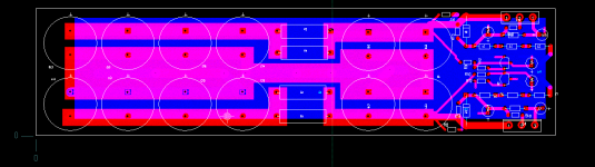
0. Equipment used, 1.jpg
1. From 20 Hz to 200KHz (with Zout=50 ohm), 3.jpg and 9.jpg
2. Gain in voltage aprox 3.5, 4.jpg, 7.jpg and 9.jpg
3. To 12 Wrms to 8 Ohm (10Vrms), appear third harmonic
13.jpg, 14.jpg, 15.jpg, 16.jpg and 17.jpg
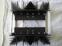
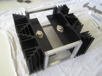
Hello jama. The assembly of your amp is impressive. You are a master at "compactness" which was my thought when I first saw its picture. I assume that the second amp will be its mirror image. Maybe put this amp in front of/next to a mirror and take a photo of the amp and its image to show the future look of your stereo amp.
- Does Zout = 50 ohm mean the output impedance of the amp; or the impedance of the load?
- Is the voltage gain ~equal to 3.5 into what load?
Thank you for your nice comments. Zout is output impedance of my function generator, so is the same (almost) that use the buffer of Mr. Pass. This gain is with a 8 ohm load, one power resistor attached to one small heatsink in the photo.
I hope during the next days I can finish the second channel, one 'mirror image'.
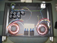
The gain is constant, I think. I used some frecuencies sine wave, from 20 to 200KHz, and I always found this 3.5 (you can see in photos of my scopemeter). For my speakers, Proac Response One 1SC, 86dB it is a little small. I need increase the gain before this ampli. But this is the next step..
Heatsink is hot (0.25 RTH), but is possible touch it with hand.
Regards
I hope during the next days I can finish the second channel, one 'mirror image'.
The gain is constant, I think. I used some frecuencies sine wave, from 20 to 200KHz, and I always found this 3.5 (you can see in photos of my scopemeter). For my speakers, Proac Response One 1SC, 86dB it is a little small. I need increase the gain before this ampli. But this is the next step..
Heatsink is hot (0.25 RTH), but is possible touch it with hand.
Regards
I sense, and am fully confident that many DYers [and I] look forward to more info, knowledge and photos from you. Congratulations for making this great build.Thank you for your nice comments. Zout is output impedance of my function generator, so is the same (almost) that use the buffer of Mr. Pass. This gain is with a 8 ohm load, one power resistor attached to one small heatsink in the photo.
I hope during the next days I can finish the second channel, one 'mirror image'.
The gain is constant, I think. I used some frecuencies sine wave, from 20 to 200KHz, and I always found this 3.5 (you can see in photos of my scopemeter). For my speakers, Proac Response One 1SC, 86dB it is a little small. I need increase the gain before this ampli. But this is the next step..
Heatsink is hot (0.25 RTH), but is possible touch it with hand.
Regards
Regards
Fifty ohms is the normative impedance of the equipment.
Today, You receive the OK.Do you Feel proud?
Congratulations countryman.
Where is ZM I miss his comments.
Best Regards.
Today, You receive the OK.Do you Feel proud?
Congratulations countryman.
Where is ZM I miss his comments.
Best Regards.
Thank you for your nice comments. Zout is output impedance of my function generator, so is the same (almost) that use the buffer of Mr. Pass. This gain is with a 8 ohm load, one power resistor attached to one small heatsink in the photo.
I hope during the next days I can finish the second channel, one 'mirror image'.
The gain is constant, I think. I used some frecuencies sine wave, from 20 to 200KHz, and I always found this 3.5 (you can see in photos of my scopemeter). For my speakers, Proac Response One 1SC, 86dB it is a little small. I need increase the gain before this ampli. But this is the next step..
Heatsink is hot (0.25 RTH), but is possible touch it with hand.
Regards
So should we be looking at an LSK front end?
My take on the Sony VFET CSX1:
This is how I'm gonna make the chassis.
Two little monoblocks with each 4 x SK88-100 (0.9K/W) heatsinks I got from the surplus store. I'll spray paint all the aluminum black.
Hardwire the Amps. Dimensions are: 220x200x100 mm.
Separate power supply in cheap *** 19" case I had laying around.
I have a feeling this would not be my last VFET Amp, so I don't use too expensive materials yet... but I do want to listen to them 😀
Any suggestions for the PSU connectors (8 pole) to the amps?
Still waiting for my Jensen they are at dutch customs....takes usually 7-10 days 🙁
Walter
Attachments

Hi WalterW
I like very much your Vfet mono blocks realisation
and concept , good example for other Diyers.
What is dutch customs transformers ?
Happy build to You 🙂
Best regards
I like very much your Vfet mono blocks realisation
and concept , good example for other Diyers.
What is dutch customs transformers ?
Happy build to You 🙂
Best regards
haha, Google translate: douanes néerlandaises 😀
Haha i was thinking about coustomised special version of Jensen transformers for Vfet amp i am sorry😀
Hello WalterW. It is a masterpiece of beauty and functionality. A lifetime keeper.My take on the Sony VFET CSX1:
This is how I'm gonna make the chassis.
Two little monoblocks with each 4 x SK88-100 (0.9K/W) heatsinks I got from the surplus store. I'll spray paint all the aluminum black.
Hardwire the Amps. Dimensions are: 220x200x100 mm.
Separate power supply in cheap *** 19" case I had laying around.
I have a feeling this would not be my last VFET Amp, so I don't use too expensive materials yet... but I do want to listen to them 😀
Any suggestions for the PSU connectors (8 pole) to the amps?
Still waiting for my Jensen they are at dutch customs....takes usually 7-10 days 🙁
Walter
Hi dady, do you mean if they will get hot?
I calculated: 36W for VFET + 15W for PSU Mosfet= 51W for one side.
2 x SK88= 0.45K/W.
51 x 0.45= +23C. Room temperature here in Holland is around 20C🙂
I calculated: 36W for VFET + 15W for PSU Mosfet= 51W for one side.
2 x SK88= 0.45K/W.
51 x 0.45= +23C. Room temperature here in Holland is around 20C🙂
Sorry my ignorance, you are instructing to me, The total temp per leg is 43 ºC taking your room Tº?
When a group like this I becoming more erudite day to day.
I planned in use one SK per Vfet maybe going to work to hot. (60.8ºC); idle current.
Thanks Walter.
Best Regards
When a group like this I becoming more erudite day to day.
I planned in use one SK per Vfet maybe going to work to hot. (60.8ºC); idle current.
Thanks Walter.
Best Regards
power supple
anyone tried a switching power supply with 2*24V?
@maybe NP is willing to answer and if for more simplicity can remove the stabilizing circuit around with the irc parts?
thanks
anyone tried a switching power supply with 2*24V?
@maybe NP is willing to answer and if for more simplicity can remove the stabilizing circuit around with the irc parts?
thanks
anyone tried a switching power supply with 2*24V?
@maybe NP is willing to answer and if for more simplicity can remove the stabilizing circuit around with the irc parts?
thanks
Me too...I have 4 pcs 24.5v /10A smps to use if its okay...
anyone tried a switching power supply with 2*24V?
So far my experience is that they work well provided that they have a good
margin for current and you filter the outputs. The filtering has to make it
down below 120 Hz, as there is a fair amount of ripple.
You can use an RC filter with a large capacitor if you provide a soft start
filter against the high possible inrush. This has the added advantage of
giving the time you might need to get the bias voltage stabilized.
😎
Hi Diyers
We have many potential buyers of Jensen transformers today 76 pieces.
Who can help finalise this GB in USA or Canada ?
http://www.diyaudio.com/forums/grou...formers-sony-vfet-project-12.html#post3894926
Thanks a lot!
Greetings
We have many potential buyers of Jensen transformers today 76 pieces.
Who can help finalise this GB in USA or Canada ?
http://www.diyaudio.com/forums/grou...formers-sony-vfet-project-12.html#post3894926
Thanks a lot!
Greetings
Attachments

- Status
- Not open for further replies.
- Home
- Amplifiers
- Pass Labs
- Article - Sony VFETs part 1