why not checking in TL431 datasheet , and having some faith in own conclusions .......

Hahaha, well yes that is exactly what I should do I suppose. Us greedy boyz can get just a bit lazy sometimes and ask questions here to shortcut having to do our own thinking 😉
I will pull up the datasheet and do the calculations. Likely it will take less than 5 minutes to do...
you always have 2.5V between adj and lower terminal
resistor in between is setting current through "adj. rail"
so , you put upper resistor , current is set by lower one , then voltages across resistors is matter of proportion
sum voltage is ...... just sum
series resistor for entire combo is allowing/setting overal current for TL431 itself , resistor divider , and loading stage/consumer
simple , isn't it
edit : just do not overcook voltage A-K , not overcook max current , not overcook resistors , and you're good
Last edited:
OK, so I did what I should in the first instance and did the calculations. I plugged it into Excel so that I could see what happens if I change R5 (3K3) and R7 (7K5) for different values of the potentiometer P1.
I can get a couple of extra volts bias and stay within the Imin for the TL431 if I drop the supply resistor (R5) and increase R7. 2K and 10K respectively look like it will work.
I will make the changes tonight and check the results.
Thanks Zen Mod!
I can get a couple of extra volts bias and stay within the Imin for the TL431 if I drop the supply resistor (R5) and increase R7. 2K and 10K respectively look like it will work.
I will make the changes tonight and check the results.
Thanks Zen Mod!
I am hoping to bias it at ~0.8A, so pretty low. This amp will just feed a tweeter in a 3-way setup so it doesn't need much grunt and I'd rather run it at a lower bias for longevity.
What are the values of your supply rails?
😎
What are the values of your supply rails?
😎
The main PSU is +/-24V or thereabouts (maybe +/-23.5V).
For the bias I am using 12V secondaries which give around 18V rectified DC so the TL431 needs to work with that to develop the bias.
Maybe I should just bias the amp a little higher, it is in a 4U 400mm deep chassis (from Modushop/HiFi-2000) so should easily cope with 1.2A or higher.
As said though, I don't need a lot of power from this amp at all. This will be feeding a 4 ohm planar tweeter crossed at 3100Hz (LR4 crossover). After a bit of reading a highpass driver over ~3000Hz only requires ~15% of total power for white noise - hence why I don't think I'll need a lot of grunt.
Are there other reasons to bias higher, nearer the specified 1.5A?
I'm wondering if mismatched N&P pair would give single-ended-ish sound by carefully controlling the 2nd harmonics.
LTSpice emulation suggests it would be possible. Output capacitor would be needed, though.
LTSpice emulation suggests it would be possible. Output capacitor would be needed, though.
Last edited:
I appreciate the answer by the master himself. Good to know my current learning process of the Zen amp design is still on track.
practically 500mV as transitional , and up to 100mV in temp. equilibrium
at least values acceptable for me
(remember that Papa is FAB (Numero Uno) , don't be surprised if he just erase m from my figures )
)
edit - for transitional value , it can go even higher , what's important is steepness of it - if DC arrives gentle , it's less critical
at least values acceptable for me
(remember that Papa is FAB (Numero Uno) , don't be surprised if he just erase m from my figures
)edit - for transitional value , it can go even higher , what's important is steepness of it - if DC arrives gentle , it's less critical
Last edited:
Adoption
ZM, Your chances for adoption were never in doubt. Now proof! H.
ya bet .........
it's stressful ...... every time I answer on something directed to Pa , I'm expecting a slap in next 3 hours (each time further diminishing my chances for adoption)
ZM, Your chances for adoption were never in doubt. Now proof! H.

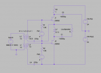
VFET Accordion Amp
I was reading TubeCad last night, and I thought Accordion Amp topology would be suitable for VFET single ended amp. LTSpice simulation suggests 2x Mu, 2X wattage than regular Sony 2SK82 SE amp, and typical SE THD figure.
I don't know if this amp works good in real world, so I ll appreciate it if someone would give me an advice. The Choke in the schematics is 0.15H 1 ohm, and R3 is for voltage compensation. Maybe a bad idea...
The Tube CAD Journal: The Accordion Amplifier: A new single-ended topology
Attachments
Last edited:
- Status
- Not open for further replies.
- Home
- Amplifiers
- Pass Labs
- Article - Sony VFETs part 1