^ Yes, and I might look at doing something a little different with the output using a trs plug and then a resistor to ground for the ring to sleeve connection to see if that helps. but the 2i2 manual clearly states that either balanced or unbalanced 1/4 inch plugs may be used 🙂
Tony.
Yeah, the 2i2 manual is too simplistic in this recommendation. 🙂 You do need to use a 3-conductor plug, but you don't need a resistor to ground on either side. You can use either +/- output and just let the other polarity float.
Carl,
I believe that unit would probably be fine. It's conceptually the same thing as the FocusRite 2i2. You just have to be careful when utilizing the inputs of these units because they configure "semi-automatically" depending upon the input plug you use and the setting of the Line/Inst switch. The input resistances and gains adjust as well when configuring. Be careful.
I have an old E-MU Tracker-Pre that I prefer. It has a 3.5mm mini jack on the back with 5VDC polarizing voltage and a 10k source resistance. I don't use the XLR/TRS jacks.
Cheers,
Dave.
Hello Ivo, I have a little question about Burst Decay. What is the difference between Time and Frequency resolution, respectively, which show the difference.
Thank you for answer
Thank you for answer
Hi,
please read my paper about detection of resonances, available from web address: http://www.artalabs.hr/papers/im-aaaa2007.pdf.
In Burst decy there is no time axis, instead ARTA shows period based axis to enable evaluation of resonances with respect to Q-factor of resonances. That way resonances are evaluated closer to perceptual hearing model.
Please do not evaluate loudspeaker responses with large level of room reflection. To get evaluation of resonances you must have almost free field measurements.
Ivo
Thanks for the info on the soudcards, guys. Maybe they should be moved off to the DAC for measurement thread, but we did use ARTA to test them. 🙂
I did some reading on the J-Test and it seems to be meant for testing jitter in AES/SPDIF transmission, nothing else. It is not valid for signals with a separate clock, or even some self clocked like HDMI. As for USB, I don't know.
I did some reading on the J-Test and it seems to be meant for testing jitter in AES/SPDIF transmission, nothing else. It is not valid for signals with a separate clock, or even some self clocked like HDMI. As for USB, I don't know.
Generally, J-test signal is constructed to maximally enhance manifestation of jitter (which can also be seen with pure sine signals). Jitter is manifestation of small changes of clock frequency. When we measure soundcard in loopback mode jitter is very small as we generate and capture signal at the same time.
Ivo
When we measure soundcard in loopback mode jitter is very small as we generate and capture signal at the same time.
Isn't latency a factor here?
Isn't latency a factor here?
As you said: "short explanation is always dull".
I have no model that can explain difference in jitter spectrum, due to latency and sequence length, but jitter spectrum surely depends on them. I recommend use of the longest FFT sequence.
How I judge soundcard clock/resolution quality is described in chapter 4.2 of ARTA manual.
There I've described how averaging lowers the dynamic range of FR measurement. The key point is that FR measurement in ARTA is cross-correlation (cross-spectrum) based, which is dependent on resolution quality and synchronicity of I/O clock. It is shown that good professional sound card can reject 20dB more of input noise than standard PC sound card.
Ivo
Hi Ivo,
I was reading Audio Precision Tech Note 23 by Julian Dunn, which I'm sure you've seen. A lot of good info there. A number of other places describe the J-Test as meant for AES type transmission.
Do you think it can show jitter suppression in other types of transport? I don't know enough about it to say one way or the other. Thanks.
Pano,
"Jitter" signal is implemented in ARTA after request for testing CD players jitter as it is done in Stereophile magazine.
Indeed this signal was defined for testing 24bit AES transmission and here is adapted for testing 16 bit signals.
There is no special magic in that signal, even pure sine of frequency fs/4 is good for monitoring spectrum side lobes introduced by jitter, but Julian Dun proposed "jitter signal" as signal that will maximally reveal jitter effects.
Best,
Ivo
I would say Dunn very specifically had suggested this type of jitter test signal to excite data related intersymbol interference effects to their maximum, in the classic manchester coded SPDIF transmission channel.
In cases outside this, it does not have any reason to exist. I do not like to use it because it can 'hide' a little bit the spurious signals showing up from the noise floor. A clean high frequency test signal at maximum amplitude is better.
Ciao, George
In cases outside this, it does not have any reason to exist. I do not like to use it because it can 'hide' a little bit the spurious signals showing up from the noise floor. A clean high frequency test signal at maximum amplitude is better.
Ciao, George
Last edited:
I would say Dunn very specifically had suggested this type of jitter test signal to excite data related intersymbol interference effects to their maximum, in the classic manchester coded SPDIF transmission channel.
In cases outside this, it does not have any reason to exist. I do not like to use it because it can 'hide' a little bit the spurious signals showing up from the noise floor. A clean high frequency test signal at maximum amplitude is better.
Ciao, George
I have nothing against your conclusion.
Ivo
Dear Ivo,
I think it is extremely useful, the inclusion of the Jtest signal in your package, still there are a lot of SPDIF interfaces in use. I just wanted to contribute in clearing up this question.
Thanks a lot for this great software.
I think it is extremely useful, the inclusion of the Jtest signal in your package, still there are a lot of SPDIF interfaces in use. I just wanted to contribute in clearing up this question.
Thanks a lot for this great software.
Hi Ivo,
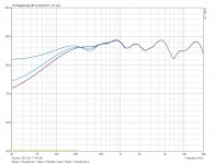
I have a problem that I hope you can shed some light on. In Fig. 1 attached, you can see 3 frequency responses that I made on an old two way loudspeaker. The Blue curve was measured using Periodic Noise and regardless of how many times I repeat this measurement with this signal source I always get precisely the same response at low frequencies.
However, when I change the signal to Log Sweep, I get inconsistent results at low frequencies as you can see from the Purple and Green curves.
All 3 measurements were made with 4 averages.
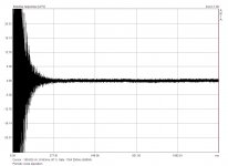
If I expand the magnitude of the impulse response to maximum as in Fig. 2, the response (using Periodic Noise) appears normal over the time period from 300mS to 1354mS, but the corresponding response using Log Sweep appears vastly different as shown in Fig.3.
All these responses were made using an M-Audio Audiophile 192 PCI sound card.
In an attempt to locate the cause of the problem I decided to purchase a new ESI Juli@ PCI sound card, only to find that this card also showed the same problem.
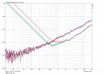
After I confirmed that this new sound card still exhibited this problem, I made a different test to see what the noise floor was by shorting the left channel input with results shown in Fig. 4. The Red, Green and Blue curves were made with the Log Sweep and the other curves with the Periodic Noise source. Hope you can help shed some light on what may be the cause of this problem.
Peter
I have a problem that I hope you can shed some light on. In Fig. 1 attached, you can see 3 frequency responses that I made on an old two way loudspeaker. The Blue curve was measured using Periodic Noise and regardless of how many times I repeat this measurement with this signal source I always get precisely the same response at low frequencies.
However, when I change the signal to Log Sweep, I get inconsistent results at low frequencies as you can see from the Purple and Green curves.
All 3 measurements were made with 4 averages.
If I expand the magnitude of the impulse response to maximum as in Fig. 2, the response (using Periodic Noise) appears normal over the time period from 300mS to 1354mS, but the corresponding response using Log Sweep appears vastly different as shown in Fig.3.
All these responses were made using an M-Audio Audiophile 192 PCI sound card.
In an attempt to locate the cause of the problem I decided to purchase a new ESI Juli@ PCI sound card, only to find that this card also showed the same problem.
After I confirmed that this new sound card still exhibited this problem, I made a different test to see what the noise floor was by shorting the left channel input with results shown in Fig. 4. The Red, Green and Blue curves were made with the Log Sweep and the other curves with the Periodic Noise source. Hope you can help shed some light on what may be the cause of this problem.
Peter
Attachments

Resolution of IR measurements
Peter,
I am very glad that you have noticed this behavior. It is actually the reason why I applied different types of excitation signals in ARTA (MLS; Swept sine and periodic noise).
I have always suggested:
1) Use noise excitation and averaging especially if you are working with large impulsive noise or with very low level signals.
2) Use swept sine without averaging and assure that you have large level of acquired signal, and low level of impulsive noise.
Problem with swept sine becomes aparent with low level signals. For good results we need to satisfiy at least 12 bit resolution. If you have lower level of acquired signal the result become biased.
So, to conclude:
for testing of soundcard resolution (noise floor) please do not use swept sine signal as resulting IR signal will be biased with an "close to DC" component.
Best regards,
Ivo
Ivo, a nontechnical question, if I may- can an ARTA license be moved from one computer to another, assuming it's uninstalled from the first computer?
Ivo, a nontechnical question, if I may- can an ARTA license be moved from one computer to another, assuming it's uninstalled from the first computer?
You may install ARTA software on all your computers.
Ivo
Hi Ivo,
Thanks for the prompt response and for explaining the Swept sine behaviour. I’ll keep those two suggestions you mentioned in mind for the future.
I have one more question for you regarding the “Frequency Domain 2Ch Averaging” button when left unchecked; does it average in the time domain? Also, it is my understanding that by averaging several responses in the time domain, you can reduce the ambient room noise when making acoustic impulse measurements, but do you get similar benefits from averaging in the frequency domain?
Peter
Last edited: