Here you have the schematic, the convertion chart to several models
and all details:
*
Also you have Greg Erskine pages:
http://users.tpg.com.au/users/gerskine/dxamp/
Also this thread and my presence here to help...it is a matter for you to manage to find some time to work on that.
regards,
Carlos
and all details:
*
Also you have Greg Erskine pages:
http://users.tpg.com.au/users/gerskine/dxamp/
Also this thread and my presence here to help...it is a matter for you to manage to find some time to work on that.
regards,
Carlos
MACD,
check transistor Q7 please.
The Assembly Guide, Carlos is talking about, shows a BD139 (E-C-B) as the VAS transistor. In case of the DX Blame SuperCharged, the Assembly Guide advises you to use a MJE15032. But the MJE15032 has a different pin configuration (B-C-E)! You should flip the MJE15032 by 180 degrees then.
Much success - Rudi
Hello Uncle Charlie,
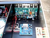
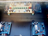
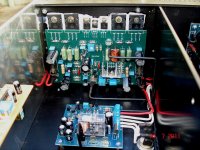
I worked on my supercharged this weekend. I checked every transistor.....all is okey. I changed Q7 from MJE15032 to MJE15030. My DC offset is now -30mV and not 100mV. I measured voltage on bais transistor and is 2.4V. Set bias to 1mv over power transistors and both positive and negative give's the same reading. Now I connect a signal and sound seems ok, but when I look on my scope my negative voltage swing or sine wave have some oscillation on. I will get a function gen tonight and test properly. All resistor and cap values are correct. What can cause my DC offset to be negative? Can you supply me with a schematic diagram with voltages to measure and check my voltages. Other then my DC offset and oscillation on negative voltage swing everything looks ok. I will post some high quality pictures of my amp. Maybe someone can see something.
Regards,
MACD
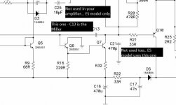
Oh!...that oscilation superimposed to negative cicle is a trouble
Try to increase the compensation capacitor, the Miller one.... increase it soldering other unit in parallel or substituting it to a higher value... 150 to 220pf may be interesting.
regards,
Carlos
Try to increase the compensation capacitor, the Miller one.... increase it soldering other unit in parallel or substituting it to a higher value... 150 to 220pf may be interesting.
regards,
Carlos
Where is Miller one....
Hi Carlos.....sorry for the ignorance, but which capacitor in the circuit is the Miller/compensation capacitor. There are 2 x 100pF caps is the circuit.
Regards,
macd😕😕😕
Try to increase the compensation capacitor, the Miller one.... increase it soldering other unit in parallel or substituting it to a higher value... 150 to 220pf may be interesting.
regards,
Carlos
Hi Carlos.....sorry for the ignorance, but which capacitor in the circuit is the Miller/compensation capacitor. There are 2 x 100pF caps is the circuit.
Regards,
macd😕😕😕
This one...increase it to 220pf if you find AC voltage
In your output terminals without signal entering the amplifier...if AC appears, this seems the amplifier is oscilating..then proceed the capacitor increasing..if no AC is present..then no need to replace.
regards,
Carlos
In your output terminals without signal entering the amplifier...if AC appears, this seems the amplifier is oscilating..then proceed the capacitor increasing..if no AC is present..then no need to replace.
regards,
Carlos
Attachments
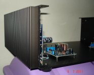

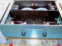
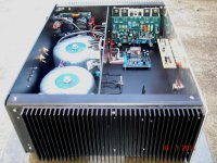

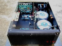
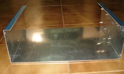
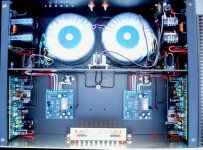
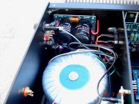

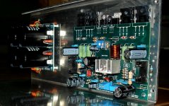


Nice and proffesional job done with those amplifiers. Wiring very neat and tidy.
Regards
niss_man
Regards
niss_man
Yes... a very impressive job he made
I will search his picture...seems he is half Japanese.
regards,
Carlos
I will search his picture...seems he is half Japanese.
regards,
Carlos
Attachments

Last edited:
I strongly suggest you to go to the group buy we have about the MKIII-Hx
And i have some reasons to explain you:
- " In the future these circuits will have the value of relics ... not only mine but all the plates produced in small numbers within this DIY forum, they will be rarities, antiquities and treasures .... amplifiers are manufactured by the thousands .... we do 50 or less kits for each model series .. little gems for their rarity, precious by the fact that you built, which creates extra value for your descendants .. one day an amplifier may be worth a lot of money for your children and grandchildren because it will be part of DIY forums, audiophile designs, will be part of the history of audio ... I'm old ... within 10 or 20 years I will be with the angels (or demons) .. then it will be worth even more, then think about it a bit. "
regards,
Carlos
After I read from the very beginning, I am interested to give it a try...it will take several time...DX is alive and kicking....
Hi guys!
I just want to show you this layout from destroyer X schematic is similar to the original, and I try to keep as accurate as possible just like his design, I posted in the wrong section on the page so I hope is the right section this time, Same as the original work for Dx Blame ES, ST, MKII, and MKII Supercharged, but to be clear for used it myself so I can enjoy good music sound, is not tested yet nor ordered, I want to thank you mister destroyer X for helping out when I have questions, I really appreciated.
An externally hosted image should be here but it was not working when we last tested it.
Attachments
Last edited:
Nice board Juan..... you must inform our friends that was not tested
That no one has built it yet.
regards,
Carlos
That no one has built it yet.
regards,
Carlos
- Status
- Not open for further replies.
- Home
- Amplifiers
- Solid State
- Are you ready to face strong emotions?.. Dx Blame MKII and the Supercharged release!