Mechanism of dead time distortion
In order to show the impact of dead time distortion a comparative measurement with original dead time setting (45ns) and
increased dead time setting (105ns) has been done.
Mechanism of dead time distortion:
A short dead time is used to ensure that upper and lower MosFets are never conductive at the same time.
During the dead time both MosFets are OFF. Consequently during dead time the voltage at the switching is not controlled by the switches, but can have any value limited only by the rails through the body diodes of the MosFets.
But even during dead time this voltage is not a random effect, but a deterministic result from the current in the inductor which charges (faster or slower or not at all) the capacitances of the snubber network and parasitic capacitances of the switches + layout.
Means during dead time the voltage of the switching node is massively depending on the load of the amplifier, instead of strictly follwing the HIGH/LOW decision of the modulator.
First attachment:
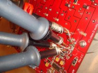
Photo of the CDA-224 with measurement Probes.
The second attachement and follwing show screen shots of the switching events:
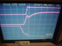
Time base: 50ns / div
Upper trace: Switching node of half bridge vs neg rail, 50V / div
Mid trace: Vgs of the high side MosFet, 5V / div
Lower trace: Vgs of the low side MosFet, 5V / div
Screen Shot 1:
Dead time setting = 45ns. Idling amp.
Short after Vgs of the lower MosFet is low enough to turn OFF the MosFet,
the switching node starts to slope upwards. This is forced by the inductive ripple current of the filter.
At the time when Vgs of the upper MosFet reaches values, which turn it ON, the switching node is already close
to the upper rail and just the last 20V are pulled up hard by the MosFet.
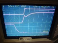
Screen Shot 2:
45ns, 0.7A output current (pointing from amp output to load)
Short after Vgs of the lower MosFet is low enough to turn OFF the MosFet,
the switching node starts to slope upwards. But much slower compared to the first screen shot,
because the 0.7A output current reduce the amount of available inductive current.
Now most of the sloping has to be forced by the upper MosFet.
Screen Shot 3:
45ns, 1.4A output current (pointing from amp output to load)
After Vgs of the lower MosFet is low enough to turn OFF the MosFet,
the switching does not start sloping, but remains at the level of the neg rail during the entire dead time.
The 1.4A output current are larger that the peak of the 400kHz filter current ripple and now the current direction
in the filter choke does not force sloping anymore, but ties the switching node to the negative rail, where it gets clamped by the body diode of the lower MosFet.
After the dead time when the upper MosFet is being turned ON, it has to remove Qrr from the body diode and then pulls up the switching node. This situation of hard switching including Qrr removal is the most demanding situation for the switching stage and poorly designed class D amps often show heavy HF ringing. The CDA-224 is handling this perfectly fine.
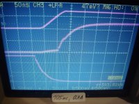
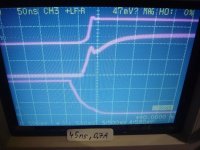
Screen Shot 4:
Dead time setting = 105ns. Idling amp.
Short after Vgs of the lower MosFet is low enough to turn OFF the MosFet,
the switching node starts to slope upwards. This is forced by the inductive ripple current of the filter.
At the time when Vgs of the upper MosFet reaches values, which turn it ON, the switching node is already fully tied
to the upper rail.
Screen Shot 5:
105ns, 0.7A output current (pointing from amp output to load)
Short after Vgs of the lower MosFet is low enough to turn OFF the MosFet,
the switching node starts to slope upwards. But much slower compared to screen shot 4,
because the 0.7A output current reduce the amount of available inductive current.
Still the switching node just reaches the upper rail before the upper MosFet is being turned ON.
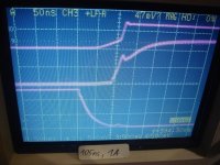
Screen Shot 6:
105ns, 1A output current (pointing from amp output to load)
Short after Vgs of the lower MosFet is low enough to turn OFF the MosFet,
the switching node starts to slope upwards. But even slower than in screen shot 5.
Now most of the sloping has to be forced by the upper MosFet.
Screen Shot 7:
105ns, 1A output current (pointing from amp output to load)
After Vgs of the lower MosFet is low enough to turn OFF the MosFet,
the switching does not start sloping, but remains at the level of the neg rail during the entire dead time.
The 1.4A output current are larger that the peak of the 400kHz filter current ripple and now the current direction
in the filter choke does not force sloping anymore, but ties the switching node to the negative rail, where it gets clamped by the body diode of the lower MosFet.
After the dead time when the upper MosFet is being turned ON, it has to remove Qrr from the body diode and then pulls up the switching node. This situation of hard switching including Qrr removal is the most demanding situation for the switching stage and poorly designed class D amps often show heavy HF ringing. The CDA-224 is handling this perfectly fine.
P.S.
You may notice that the displayed frequency sometimes is close to 400kHz and sometimes zero.
There is no relevance behind - for some reason this scope has an always active frequency display.
When I was to lazy to turn OFF the amp during writing the labels and taking the photos of the stored event,
then the screen shot shows the switching frequency of the amp.
In order to show the impact of dead time distortion a comparative measurement with original dead time setting (45ns) and
increased dead time setting (105ns) has been done.
Mechanism of dead time distortion:
A short dead time is used to ensure that upper and lower MosFets are never conductive at the same time.
During the dead time both MosFets are OFF. Consequently during dead time the voltage at the switching is not controlled by the switches, but can have any value limited only by the rails through the body diodes of the MosFets.
But even during dead time this voltage is not a random effect, but a deterministic result from the current in the inductor which charges (faster or slower or not at all) the capacitances of the snubber network and parasitic capacitances of the switches + layout.
Means during dead time the voltage of the switching node is massively depending on the load of the amplifier, instead of strictly follwing the HIGH/LOW decision of the modulator.
First attachment:
Photo of the CDA-224 with measurement Probes.
The second attachement and follwing show screen shots of the switching events:
Time base: 50ns / div
Upper trace: Switching node of half bridge vs neg rail, 50V / div
Mid trace: Vgs of the high side MosFet, 5V / div
Lower trace: Vgs of the low side MosFet, 5V / div
Screen Shot 1:
Dead time setting = 45ns. Idling amp.
Short after Vgs of the lower MosFet is low enough to turn OFF the MosFet,
the switching node starts to slope upwards. This is forced by the inductive ripple current of the filter.
At the time when Vgs of the upper MosFet reaches values, which turn it ON, the switching node is already close
to the upper rail and just the last 20V are pulled up hard by the MosFet.
Screen Shot 2:
45ns, 0.7A output current (pointing from amp output to load)
Short after Vgs of the lower MosFet is low enough to turn OFF the MosFet,
the switching node starts to slope upwards. But much slower compared to the first screen shot,
because the 0.7A output current reduce the amount of available inductive current.
Now most of the sloping has to be forced by the upper MosFet.
Screen Shot 3:
45ns, 1.4A output current (pointing from amp output to load)
After Vgs of the lower MosFet is low enough to turn OFF the MosFet,
the switching does not start sloping, but remains at the level of the neg rail during the entire dead time.
The 1.4A output current are larger that the peak of the 400kHz filter current ripple and now the current direction
in the filter choke does not force sloping anymore, but ties the switching node to the negative rail, where it gets clamped by the body diode of the lower MosFet.
After the dead time when the upper MosFet is being turned ON, it has to remove Qrr from the body diode and then pulls up the switching node. This situation of hard switching including Qrr removal is the most demanding situation for the switching stage and poorly designed class D amps often show heavy HF ringing. The CDA-224 is handling this perfectly fine.
Screen Shot 4:
Dead time setting = 105ns. Idling amp.
Short after Vgs of the lower MosFet is low enough to turn OFF the MosFet,
the switching node starts to slope upwards. This is forced by the inductive ripple current of the filter.
At the time when Vgs of the upper MosFet reaches values, which turn it ON, the switching node is already fully tied
to the upper rail.
Screen Shot 5:
105ns, 0.7A output current (pointing from amp output to load)
Short after Vgs of the lower MosFet is low enough to turn OFF the MosFet,
the switching node starts to slope upwards. But much slower compared to screen shot 4,
because the 0.7A output current reduce the amount of available inductive current.
Still the switching node just reaches the upper rail before the upper MosFet is being turned ON.
Screen Shot 6:
105ns, 1A output current (pointing from amp output to load)
Short after Vgs of the lower MosFet is low enough to turn OFF the MosFet,
the switching node starts to slope upwards. But even slower than in screen shot 5.
Now most of the sloping has to be forced by the upper MosFet.
Screen Shot 7:
105ns, 1A output current (pointing from amp output to load)
After Vgs of the lower MosFet is low enough to turn OFF the MosFet,
the switching does not start sloping, but remains at the level of the neg rail during the entire dead time.
The 1.4A output current are larger that the peak of the 400kHz filter current ripple and now the current direction
in the filter choke does not force sloping anymore, but ties the switching node to the negative rail, where it gets clamped by the body diode of the lower MosFet.
After the dead time when the upper MosFet is being turned ON, it has to remove Qrr from the body diode and then pulls up the switching node. This situation of hard switching including Qrr removal is the most demanding situation for the switching stage and poorly designed class D amps often show heavy HF ringing. The CDA-224 is handling this perfectly fine.
P.S.
You may notice that the displayed frequency sometimes is close to 400kHz and sometimes zero.
There is no relevance behind - for some reason this scope has an always active frequency display.
When I was to lazy to turn OFF the amp during writing the labels and taking the photos of the stored event,
then the screen shot shows the switching frequency of the amp.
Attachments


Consequences of dead time distortion
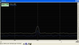
The mechanism of dead time distortion is leading to distortions, especially long dead time results in
an unpleasant broadband "splatter" of harmonics.
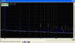
In case of the CDA-224 an increase of the dead time setting from 45ns to 105ns boosts up most of the
higher order harmonics by 10...15db. The 9th grows more than 20db....
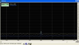
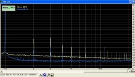
The attached files show the comparison of the distortion spectrum with 45ns and 105ns, when driving a resitive 4R load with 10W.
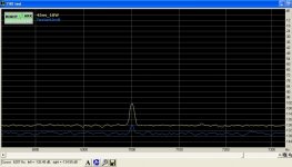
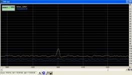
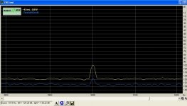
First the full spectrum 1kHz..20kHz, then some zoomed details on 5th, 7th and 9th.
Such figures are not a specific short coming of this implementation - but the distortion mechanism is in the nature of half bridge / full bridge based class D amps with ordinary PWM modulator.
Obviously the precision in the control of the MosFets is a key topic for low distortion.
This also points to the fact that high power class D amplifiers obviously give more design challenge, not just because of power handling, but also regarding distortion figures. Controlling heavy MosFets with the precision of a few ns is a demanding topic, but possible.
The mechanism of dead time distortion is leading to distortions, especially long dead time results in
an unpleasant broadband "splatter" of harmonics.
In case of the CDA-224 an increase of the dead time setting from 45ns to 105ns boosts up most of the
higher order harmonics by 10...15db. The 9th grows more than 20db....
The attached files show the comparison of the distortion spectrum with 45ns and 105ns, when driving a resitive 4R load with 10W.
First the full spectrum 1kHz..20kHz, then some zoomed details on 5th, 7th and 9th.
Such figures are not a specific short coming of this implementation - but the distortion mechanism is in the nature of half bridge / full bridge based class D amps with ordinary PWM modulator.
Obviously the precision in the control of the MosFets is a key topic for low distortion.
This also points to the fact that high power class D amplifiers obviously give more design challenge, not just because of power handling, but also regarding distortion figures. Controlling heavy MosFets with the precision of a few ns is a demanding topic, but possible.
Attachments


Markus, you might not have sent the right attachments with your last post, and I am curious to actually see the difference.
Hi Vac,
which kind of attachments would you have expected?
To me they are looking like intended.
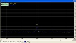
All graphs show two lines, where the blue line is showing the spectrum with a dead time setting of 45ns and the yellow line is showing the spectrum with a dead time setting of 105ns.
Starting from 5th order the yellow peaks are significantly higher than the blue peaks, especially for the odd orders.
In numbers:
k5: -102db with 45ns but -89db with 105ns ==> worsening by enlarged dead time: 13db
k7: -103db with 45ns but -88db with 105ns ==> worsening by enlarged dead time: 15db
k9: -115db with 45ns but -91db with 105ns ==> worsening by enlarged dead time: 24db
which kind of attachments would you have expected?
To me they are looking like intended.
All graphs show two lines, where the blue line is showing the spectrum with a dead time setting of 45ns and the yellow line is showing the spectrum with a dead time setting of 105ns.
Starting from 5th order the yellow peaks are significantly higher than the blue peaks, especially for the odd orders.
In numbers:
k5: -102db with 45ns but -89db with 105ns ==> worsening by enlarged dead time: 13db
k7: -103db with 45ns but -88db with 105ns ==> worsening by enlarged dead time: 15db
k9: -115db with 45ns but -91db with 105ns ==> worsening by enlarged dead time: 24db
I have listend a lot to the mk3 version
Lyngdorf Audio - Millennium Mk IV
It's the best amplifier I have heard, and I have been able to AB test with several other amplifiers many different loudspeakers. I love it because it's very revealing. A music producer was also impressed and have never heard such an revealing amplifier, but would never buy it himself, because he could also here the errors in the production or were the cuts were made. Therefore he preffered a more foregiving amplifier.
Now I see it, had to turn on the brightness of my screen. The dark blue was kind of black on my first try. Now I can discern it, no further discussion possible, you have proven your point completely, thanks for showing.
I also love NAD 3020 and Dali Gravity. I dont count the differences of any given well designed amplifier as major differences
Now I see it, had to turn on the brightness of my screen. The dark blue was kind of black on my first try ....
...understood..., well I had chosen these colours in order to make the high peaks of 105ns line better visible, especially for the first screen shot.
But yes, this choice made the blue 45ns line almost invisible..
I also love NAD 3020 and Dali Gravity. I dont count the differences of any given well designed amplifier as major differences
From my point of view the classD amps have reached a respectable level and can satisfy in many cases.
Still the final subjective rating is likely to differ even more than the engineers opinions on what is designed well and what not.
The subjective discussions are fun when I am sitting together with a friend and we can listen to the same equipment(s). But just by writing and reading it is really hard to derive a valid 'sound image' in my brain.
Our perception is very subjective, writing also allows no objective describtion of the sound (except for really catastrophic sounding equipment) and in the end our way of interpretation during reading is again subjective. With all these unspecified 'transfer functions' in our communication chain one has to expect a pretty annoying amount of misunderstandings. That's why I am putting in this forum more weight on the technical topics and comment the sound just sometimes.
Thank you for testing this excellent (one could easily say "flawless") amplifier. But one must note that the spectrum analyzer shots you posted do not support the description of "broadband splatter" . . . if any "splatter" exists it is below the (very low) noise floor of your test system. Just as it is well below the noise floor of any available recording/delivery system.The mechanism of dead time distortion is leading to distortions, especially long dead time results in
an unpleasant broadband "splatter" of harmonics.
What you do show is that using the amplifier as delivered there is no dead time induced "splatter" and any distortion components are more than 100dB down . . . certainly inaudible. Even after mal-adjusting the amplifier you couldn't get harmonics to rise above 90dB down, and there's still no "dead time splatter".
If any amplifier sounds "different" from this it is broken, and spending more money on Class A or Class AB is simply to waste it (the money, that is). And that's not just for subwoofers . . .
Thank you for testing this excellent (one could easily say "flawless") amplifier.***
An amp can only be called "flawless" if it maintains a constant frequency response regardless of the driven load. Unlike the Hypex, ICEpower ASX2, and a few others, the CDA designs do not seem to meet this key criterion.
Most D's don't, and that's the main reason when they verifiably sound different.
Distortion can be important. Frequency response always is.
Last edited:
Maybe that's your "key criterion", but it's not mine. Has no significance at all for me, in fact, since any effect is confined to tweeter response, something I always "tune" anyway, and there the CDA's "load sensitivity" almost always works in my favor. Frequency response "adjustment" is an essential part of any system design, and the possibly differing response of pre and post filter feedback designs is not a "flaw" either way. It's completely predictable, and simply becomes another part of the crossover/loudspeaker/system design.An amp can only be called "flawless" if it maintains a constant frequency response regardless of the driven load. Unlike the Hypex, ICEpower ASX2, and a few others, the CDA designs do not seem to meet this key criterion.
The CDA amps (and the Chinese "reference amp" implementations as well) are "board level" components, for users whose "DIY" ability is enough beyond merely swapping amps and cables that addressing load effects is a trivial exercise.
. . if any "splatter" exists it is below the (very low) noise floor of your test system.....
Come on !
By comparing posting #40 & #42 you can see, that the limits of the measurement system are proven clearly better than the unmodified original amp, except k8 & k11.
For reference I am attaching the direct comparison of the unmodified original amp (dead time setting 45ns) vs the test system.
...well, to me even the spectrum of the unmodified amp looks a little bit like spl... 😀 , but most amps do - and IMHO in the region of -100db this is not a catastrophy.What you do show is that using the amplifier as delivered there is no dead time induced "splatter" and any distortion components are more than 100dB down . . .
Furtheron if you can easily turn the moderate peaks into skyscrapers simply by increasing the dead time just a few ns then this is a nice visualisation that the mechanism of dead time distortion introduces a pretty unpleasant spectrum of distortion.
I am not saying that classD is bad, I am also not saying the CDA244 would be bad. IMHO the distortion figures of the CDA224 are pretty good.
I am just disagreeing that classD would inherently better than class AB, because of the absence cross over related high order harmonics.
Both technologies can be brought to reasonably low amount of high order harmonics, but both are suffering from unpleasant distortion effects which are related to the use of two power devices, whereoff one is needed to provide positive currents into the load while the other is needed to provide negative currents.
And I am saying that the classD technology is less mature than classAB, which leads to a larger spread of design quality in the market place.
P.S.
From my perspective my sound card is not really great.
The harmonics are OK, but the noise floor is just so so.
Regarding the noise floor: Don't let you get tricked by the graph of spectral density. If in this graph the noise floor is at -134db, this does not mean the S/N ratio would be that low. In order to derive the S/N ratio from the spectral density we have to integrate it over the bandwidth and we will get a pretty frustrating result. Even with the A-weighting, which gives slightly nicer numbers again, it is not great.
Attachments
-
 k8_orig_vs_tester.JPG84.9 KB · Views: 54
 -
 k7_orig_vs_tester.JPG83.6 KB · Views: 61
 -
 k6_orig_vs_tester.JPG83.2 KB · Views: 64
 -
 k5_orig_vs_tester.JPG83.5 KB · Views: 289
 -
 k4_orig_vs_tester.JPG81.7 KB · Views: 284
 -
 k3_orig_vs_tester.JPG81.5 KB · Views: 291
 -
 k2_orig_vs_tester.JPG92.1 KB · Views: 296
 -
 Spectrum_orig_vs_tester.JPG93.4 KB · Views: 291
 -
 k9_orig_vs_tester.JPG87 KB · Views: 55
Last edited:
It seems that we use "splatter" differently . . . to me splatter is nonharmonically related distortion. But we do agree in that -100dB is not . . . catastrophic . . ....well, to me even the spectrum of the unmodified amp looks a little bit like spl... 😀 , but most amps do - and IMHO in the region of -100db this is not a catastrophy.
Um . . . yes . . . "pretty good". My system is set up so that with the volume at "full" 0dBfs produces 105dB at the listening position. The combined noise floor, microphone to listening room, is at best 25dB (and typically above that). A "distortion component" that is 100dB down would not be heard even completely isolated from the originating signal . . . with a simultaneous 105dB broadband (music) signal it would not be heard, period. I'd call that "pretty good enough" . . . 😀IMHO the distortion figures of the CDA224 are pretty good.
Well . . . IMO and to my ear the crossover related splatter from typical Class AB amps is enough worse to be audible, and annoying. There are certainly examples where it is not . . . LM3886 "chip amps", for example, have excellent bias tracking and no audible crossover distortion in normal operation. Adcom produced some Class AB bipolar amps that beat the problem (their MOSFET amps maybe not so much). Doug Self wrote a whole chapter in his amplifier book on how to avoid it. None are better than the lowly Class D amp board you just tested. It's "pretty good enough" . . . and certainly "not just for sub-woofers" . . .I am just disagreeing that classD would inherently better than class AB, because of the absence cross over related high order harmonics.
I have listend a lot to the mk3 version
Lyngdorf Audio - Millennium Mk IV
It's the best amplifier I have heard, and I have been able to AB test with several other amplifiers many different loudspeakers. I love it because it's very revealing. A music producer was also impressed and have never heard such an revealing amplifier, but would never buy it himself, because he could also here the errors in the production or were the cuts were made. Therefore he preffered a more foregiving amplifier.
Is this a class-d amp ? it weighs 25Kilos ......
It seems that we use "splatter" differently . . . to me splatter is nonharmonically related distortion. But we do agree in that -100dB is not . . . catastrophic . . .
Um . . . yes . . . "pretty good". My system is set up so that with the volume at "full" 0dBfs produces 105dB at the listening position. The combined noise floor, microphone to listening room, is at best 25dB (and typically above that). A "distortion component" that is 100dB down would not be heard even completely isolated from the originating signal . . . with a simultaneous 105dB broadband (music) signal it would not be heard, period. I'd call that "pretty good enough" . . . 😀
Well . . . IMO and to my ear the crossover related splatter from typical Class AB amps is enough worse to be audible, and annoying. There are certainly examples where it is not . . . LM3886 "chip amps", for example, have excellent bias tracking and no audible crossover distortion in normal operation. Adcom produced some Class AB bipolar amps that beat the problem (their MOSFET amps maybe not so much). Doug Self wrote a whole chapter in his amplifier book on how to avoid it. None are better than the lowly Class D amp board you just tested. It's "pretty good enough" . . . and certainly "not just for sub-woofers" . . .
Not even good for subwoofer amps , Imo class-a or a/b amplifiers are better at the freq extremes , hence better bass than class -d ....
Listening test where we have compared them (never heard Hypex, we compared BelCanto and Rotel) the class A/B and Class -a were all better in the Bass..
YMMV
YMMV
Last edited:
That sounds like a very controlled environment! C'mon, don't insult our intelligence. How can you make blanket statements about a whole class of amplification based on what some guys in a room think about a couple of different amps.
Yes how dare us buy amplifiers and listen to them when we have you to tell us what to think ..🙄
No wonder audio is dead ...
No wonder audio is dead ...

- Status
- Not open for further replies.
- Home
- Amplifiers
- Class D
- Are class D amplifier only good for subwoofer speakers ?