Hi after updating our Hi-fi setup wanted to Recompile the code..
We lost the old code so we download the firmware_LDR_v1.0
update our inputs and reflashed the Nano.
when turning on the device it shows the welcome screen, after 1 sec or so. a relay clicks and the Nano seems to reboot.
what we tried
Going back to the Arduino IDE 1.6.10.
Used the old library versions and it still shows boot screen and reboots
Unfortunately, I cannot give a better advice than putting debug outputs like Serial.print() at all the entries and exits of all subfunctions to see which was the function that was called before the crash using the serial monitor.
Hi after updating our Hi-fi setup wanted to Recompile the code..
We lost the old code so we download the firmware_LDR_v1.0
update our inputs and reflashed the Nano.
when turning on the device it shows the welcome screen, after 1 sec or so. a relay clicks and the Nano seems to reboot.
what we tried
Going back to the Arduino IDE 1.6.10.
Used the old library versions and it still shows boot screen and reboots
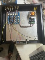
What board are you using? What display? What remote? Photos please.
In case it helps anybody my final code for LCDs with impedance adjustment is in post 1193. Uses Apple remote and needs ide 1.65
Hello. There is a desire to build this controller. I plan to develop the board myself for my own design. In this regard, I have a question.
Please tell me how best to divide the circuit (separate the digital part from the analog part). It is clear that the input and output sockets of the RCA, the input switching
relay, the calibration relay ULN2003 MCP23008 will be located on the board mounted on the BACK wall. Microcontroller, controls, IR -on the FRONT panel.
Is it possible to control the control scheme
Place the LDR NSL32 on the microcontroller board, the length of the links will be about 30 cm.(The number of wires between the boards in this case is minimal)
Or does the control circuit have to be located next to the LDR NSL32 on the board with the input sockets?
(The number of wires between the boards in this case is maximum).
Sorry for my English, I use a translator. Thanks

- Home
- Source & Line
- Analog Line Level
- Arduino based LDR volume and source selection controller