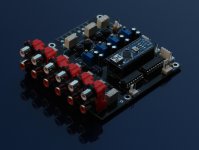
Inside the menu and volume control works fine. The only problem is at the welcome screen
Hm, interesting. It's not in the code to print anything below 2nd line, not sure where it got lost. I guess no one used last two lines up to now😉
I updated the VxD_LCD_4x2, try it now. I don't have LCD 2004 so cannot test.
Unfortunately the code doesn’t work it doesn’t boot at all.
I also have another problem can’t set bias at RSH it shows 64ohm. I have changed the ldr then the Q3 but nothing changed🙁
I also have another problem can’t set bias at RSH it shows 64ohm. I have changed the ldr then the Q3 but nothing changed🙁
Unfortunately the code doesn’t work it doesn’t boot at all.
I also have another problem can’t set bias at RSH it shows 64ohm. I have changed the ldr then the Q3 but nothing changed🙁
compare DC voltages between Q1 and Q3.
I just tested LCD code and it works fine in both 2004 and 1602 modes. You need to set it here:
#define LCDTYPE 2004 // Specify the LCD type. Only 2004 and 1602 are supported
do not change LCDCOLUMNS and LCDROWS directly.
#define LCDTYPE 2004 // Specify the LCD type. Only 2004 and 1602 are supported
do not change LCDCOLUMNS and LCDROWS directly.
I changed the lcd address and works although a bit darker but at the 3rd and 4th line appears the message that is at the 1st and 2nd line.
Please explain me how to measure the voltage between q1 & q3
Please explain me how to measure the voltage between q1 & q3
Last edited:
Hello and thanks to all the people who know much more about electronics than me for working on this amazing project.
I have a question: Is it possible to integrate a DSP before the volume control, but after the Input Selector?
Or in other words: What would be the smartest way to integrate a DSP?
I have a question: Is it possible to integrate a DSP before the volume control, but after the Input Selector?
Or in other words: What would be the smartest way to integrate a DSP?
I changed the lcd address and works although a bit darker but at the 3rd and 4th line appears the message that is at the 1st and 2nd line.
Please explain me how to measure the voltage between q1 & q3
Measure voltage between S,G,D pins and ground, and compare them to other transistors.
Hello and thanks to all the people who know much more about electronics than me for working on this amazing project.
I have a question: Is it possible to integrate a DSP before the volume control, but after the Input Selector?
Or in other words: What would be the smartest way to integrate a DSP?
If you don't plan to use analog sources, better to implement volume control directly in DSP.
Gate and source have the voltages of source and gate of the others.
Measure voltage between S,G,D pins and ground, and compare them to other transistors.
Gate and source have the voltages of source and gate of the others.
Q1 and Q3 should have similar values on all the pins. If one of them is off, you should troubleshoot from there.
Found the problem at the code and now works fine.
Please update it at your google drive.
// display welcome message
lcd.begin(LCDCOLUMNS, LCDROWS);
lcd.clear();
lcd.backlight();
lcd.setCursor((LCDCOLUMNS + 1 - sizeof(msgWelcome1)) / 2, 0);
lcd.print(msgWelcome1);
lcd.setCursor((LCDCOLUMNS + 1 - sizeof(msgWelcome2)) / 2, 1);
lcd.print(msgWelcome2);
#if LCDCOLUMNS == 20
lcd.setCursor((LCDCOLUMNS + 1 - sizeof(msgWelcome3)) / 2, 2);
lcd.print(msgWelcome1=>3);
lcd.setCursor((LCDCOLUMNS + 1 - sizeof(msgWelcome4)) / 2, 3);
lcd.print(msgWelcome2=>4);
#endif
Yeah shotgun that!I've got another assembled kit, with or without PS, if anyone is interested. You just need to add a box and a remote.
I sent you a PM.
Cheers
I've bought this crimping tool for crimping these pins from the original BOM.
The quality of the tool is fine but it is not useful for the purpose. It is around 5mm thick so it squeezes both sets of "arms" at the same time. Besides that the whole pin seems to get twisted.
How can I crimp a cable to those pins? I tried manually with a flat pliers, which seemed to be a PITA.
The quality of the tool is fine but it is not useful for the purpose. It is around 5mm thick so it squeezes both sets of "arms" at the same time. Besides that the whole pin seems to get twisted.
How can I crimp a cable to those pins? I tried manually with a flat pliers, which seemed to be a PITA.
- Home
- Source & Line
- Analog Line Level
- Arduino based LDR volume and source selection controller
