What version used?I can't open this using eagle.Hello Theodosis,
The board is 94x66 mm. You can open the board file with Eagle to see exactly its dimensions and mounting holes.
What version used?I can't open this using eagle.
Try this:
Freeware | Get the EAGLE Light Edition free | CadSoft EAGLE
I have the eagle ver. 5.8 but i can't open this file.
Eagle ver. 5.8 is pretty old. The current version is 7.4.0.
I can open the files just fine with v.7.2.0.
I can open the files just fine with v.7.2.0.
Hi Vincent,
Interesting potential problem I have:
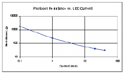
In the code, you comment saying minimum LDR resistance should be less than 100 ohms, and to replace if higher than that when measuring them.
Currently, I'm getting between about 250 and 500 ohms, so it would seem I should replace them. However, measuring current on the photocell side, I only get a current of around 3.3 mA. And looking at the datasheet of the NSL-32SR2, that's probably out a bit but not by much...
What do you think?
Interesting potential problem I have:
In the code, you comment saying minimum LDR resistance should be less than 100 ohms, and to replace if higher than that when measuring them.
Currently, I'm getting between about 250 and 500 ohms, so it would seem I should replace them. However, measuring current on the photocell side, I only get a current of around 3.3 mA. And looking at the datasheet of the NSL-32SR2, that's probably out a bit but not by much...
What do you think?
Attachments
Last edited:
I'm not too worried about a little bit of attenuation at "full volume", I'm putting the output through another op-amp buffer anyway.
Presumably the calibration will result in going with the highest-value series/shunt ratio so at maximum volume, the attenuation is matched between left and right?
Presumably the calibration will result in going with the highest-value series/shunt ratio so at maximum volume, the attenuation is matched between left and right?
tfboy, in case it helps here are the values I got during setup :
// if any measured value is > 200 ohm, replace the LDR. Normal values are around 100 ohm.
#define LDR_LSE_MIN 62.5 //** measured value of left series LDR R at maximum current
#define LDR_LSH_MIN 161.8 //** measured value of left shunt LDR R at maximum current
#define LDR_RSE_MIN 72.5 //** measured value of right series LDR R at maximum current
#define LDR_RSH_MIN 133.9 //** measured value of right shunt LDR R at maximum current
Hmm. Thanks wineds. 🙂
I've changed a few of the NSL-32SR2, but my measured values are consistently over the 200 ohm mark.
I've currently built the circuit on a breadboard for testing. Power is coming from two regulated bench PSUs (one for 12V for relays and audio, the other for 8V for the Arduino). On the 12V, I'm only getting a total current draw of around 8-10mA in measurement mode which is probably a bit on the low side: if divided into four, that's around 2.5mA per LDR which seems rather low and probably explains the relatively high resistance...
Hmm. Thanks wineds. 🙂
I've changed a few of the NSL-32SR2, but my measured values are consistently over the 200 ohm mark.
I've currently built the circuit on a breadboard for testing. Power is coming from two regulated bench PSUs (one for 12V for relays and audio, the other for 8V for the Arduino). On the 12V, I'm only getting a total current draw of around 8-10mA in measurement mode which is probably a bit on the low side: if divided into four, that's around 2.5mA per LDR which seems rather low and probably explains the relatively high resistance...
OK :
1. Did the Bias adjust OK as per 4.3 in the manual?
2. Are you sure the 2.2k and 33K resistors are the correct value as per R32, 34?
3. Are the connections between the above mentioned resistors and the Ardinio intact?
4. Are the FETs of the type in the BOM?
Just realised my silly mistake. 😱
As it's on the breadboard, I hadn't wired in the resistive side of the LDRs through the relays, so they were constantly switched to the 5V through precision 10k resistor which was biasing the results.
When going in to measure the LDR values, the relays are released so the resistive side should be open circuit (going through the audio input and output circuit).
Having the resistor side open circuit measures sensible: 72, 136, 73 and 115 🙂
Just realised my silly mistake. 😱
As it's on the breadboard, I hadn't wired in the resistive side of the LDRs through the relays, so they were constantly switched to the 5V through precision 10k resistor which was biasing the results.
When going in to measure the LDR values, the relays are released so the resistive side should be open circuit (going through the audio input and output circuit).
Having the resistor side open circuit measures sensible: 72, 136, 73 and 115 🙂
Well done tfboy. Have you done a listening test yet?
No, I'm now stuck on calibration. It comes up with an error 1 or 2. I haven't sussed out yet if relays should stay on. Code suggests they should, but I get an error nonetheless.
I've resorted to having a batch of PCBs made up, at least it will allow relays to be properly connected.
I've resorted to having a batch of PCBs made up, at least it will allow relays to be properly connected.
Vincent, for now I have worked around the issue by substituting pulseIn with newpulseIn in getIRkey.
Code for newpulseIn can be found here :
https://downloadcode.wordpress.com/2011/01/10/code-for-buffalo-ii-dac-vb06e/
However "repeat" no longer works. But the system in now usable and mute key also now works reliably.
Vincent, I have managed to patch the code to get repeat to also work now. Only residual issue I have now is sometimes volume goes one step in the wrong direction after a remote up/down keypress. I need to observe this more closely to determine the conditions that lead to this.
Hey, I'm back.
I still can't understand why my IR remote works perfectly and yours does not.
I am using an aluminum Apple remote. There is a 0.1µ capacitor soldered between pins "+" and "GND" of the IR receiver - check whether you didn't solder it by mistake in the wrong position.
There is a difference, though - in my prototype I used a TSOP32438 IR receiver, and in the BOM I specified a TSOP34438. But only the pinout is different between the two, the receiver should behave in the same way! Could this be the cause?
Sorry for the basic question but is this LCD suitable I2C Arduino LCD 2004 20x4 Character LCD Module Blue Backlight for Arduino Pi Pic | eBay
If not could some one recommend one and I can try and compare to ones I can find on ebay.
Thanks
Mark.
If not could some one recommend one and I can try and compare to ones I can find on ebay.
Thanks
Mark.
Sorry for the basic question but is this LCD suitable I2C Arduino LCD 2004 20x4 Character LCD Module Blue Backlight for Arduino Pi Pic | eBay
Yes, that's the one - I2C interface and 20x4 size.
Thanks Vincent, Ill order one of those or have a scout around for a slightly cheaper one first. An arduino nano is already on its way to me, Ill get onto searching for the other components and ordering PCBs a little later, Im supposed to be house shopping but keep getting distracted 😱
Hey, I'm back.
I still can't understand why my IR remote works perfectly and yours does not.
I am using an aluminum Apple remote. There is a 0.1µ capacitor soldered between pins "+" and "GND" of the IR receiver - check whether you didn't solder it by mistake in the wrong position.
There is a difference, though - in my prototype I used a TSOP32438 IR receiver, and in the BOM I specified a TSOP34438. But only the pinout is different between the two, the receiver should behave in the same way! Could this be the cause?
I don't have any TSOP32438 handy but I tried one of these today with your original source :
http://download.altronics.com.au/files/datasheets_Z1611A.pdf
Same behaviour as for the TSOP34438. I am using IDE 1.6.5 in case that matters? Could it be the libraries? I remember you subsequently posted them.
Hi Vincent,
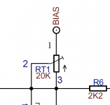
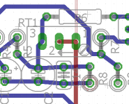
I'm probably being really dumb here 😱 but I cannot in my head understand the mapping of the circuit from the schematic to the PCB.
Taking for example the variable trimmer pot RT1, let's say pin 1 is at the top and goes to Bias, pins 2 (middle variable one) and 3 are shorted together and go to R5, C2, C14, R6 and R8.
Looking at the Eagle PCB routing, the Bias pin 1 next to the pot screw is shorted with the middle pin 2. Pin 3 goes to R5, C2, C14...
So the PCB drawing shorts pins 1 and 2 whereas the schematic shorts pins 2 and 3.
Have I misunderstood something?
Attachments
- Home
- Source & Line
- Analog Line Level
- Arduino based LDR volume and source selection controller