... finished!
Can you check the schematics? I want to order PCB' s (without fourth board: needs from customers more options and features!)...
Wow, you put a lot of work in it!
Looks good.
You don't need diodes on relay coils (the ULN2003 has them inside).
... finished!
Can you check the schematics? I want to order PCB' s (without fourth board: needs from customers more options and features!)...
Looks very good JPS! A few minor nit picking things :
1. I think the final result would look better if the encoder and the power switch were all located on the display centreline?
2. I think it would good if this could be put into standby using the remote. Is this possible? The display would need to be blanked and the LDRs set to lowest current to preserve them. Is this possible with the current design?
Hi Vincent,
I've tried to compile the code but without any success. I have loaded the PinChangeInterrupt library available to download, but when verifying, it complains:
Are there other customised / specific libraries that should be loaded?
I've tried to compile the code but without any success. I have loaded the PinChangeInterrupt library available to download, but when verifying, it complains:
Code:
firmware_LDR_v1.0.ino: In function 'void attachInterrupts()':
firmware_LDR_v1.0:1369: error: 'PCintPort' has not been declared
'PCintPort' has not been declared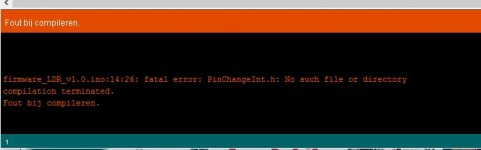
Indeed, I forgot to mention the libraries.
Just copy the contents of this archive in the My Documents\Arduino\libraries folder, or follow the instructions here: https://www.arduino.cc/en/Guide/Libraries
Just copy the contents of this archive in the My Documents\Arduino\libraries folder, or follow the instructions here: https://www.arduino.cc/en/Guide/Libraries
Attachments
Nice! Thank You for sharing it. Isn't possible to replace the relays with LDRs too?
The input / output relays - yes, they could be replaced with LDRs.
The calibration relays - maybe, it would take 5 LDRs to do it.
But the latching Ag-Pd contact relays I'm using are top quality already.
Hi Vincent,
I'm learning Arduino IDE so in the process of deciphering the code, but regarding the I/O side of things: if we have one and one only (fixed) output, then can that not free up R5 to control another input?
I think that's what the code suggests:
Your instructions suggest up to 6 I/O and you cover a variery of cases and say 3 In + 3 Out not possible, but the examples only state up to 4 In + 2 Out and no indication whether 5 In + 1 Out is possible...
I love how you've put this together. It's very tidy 😎
I'm learning Arduino IDE so in the process of deciphering the code, but regarding the I/O side of things: if we have one and one only (fixed) output, then can that not free up R5 to control another input?
I think that's what the code suggests:
Code:
#if INPUTCOUNT > 0
	if (millis() - mil_onInput > TIME_RELAYLATCH) {
		lcd.setCursor(1, ROW_IN);
		lcd_print(inputName[chan_in], 9);

#if INPUTCOUNT > 2 // inputs are on R1 to R4
		for (byte i = 0; i < INPUTCOUNT; i++)
			if (i != chan_in)
				mcp.digitalWrite(relayMap[i], LOW);
		mcp.digitalWrite(relayMap[chan_in], HIGH);

#elif INPUTCOUNT <= 2 && OUTPUTCOUNT <= 2 // inputs are on R1
		if (chan_in)
			mcp.digitalWrite(PIN_EXT_R1, HIGH);
		else
			mcp.digitalWrite(PIN_EXT_R1, LOW);

#else // inputs are on R5
		if (chan_in)
			mcp.digitalWrite(PIN_EXT_R5, HIGH);
		else
			mcp.digitalWrite(PIN_EXT_R5, LOW);
#endif
		mil_onInput = millis();
	}
#endif
}I love how you've put this together. It's very tidy 😎
if we have one and one only (fixed) output, then can that not free up R5 to control another input?
Hi,
Good question!
Indeed, if you only have one fixed output (or input), you can use R5 to control another input (or output).
You can even use R6, too - if you don't use the delay feature.
If you need 5 or 6 input (or output) channels, you will need to slightly modify the setInput() and/or setOutput() functions in the code. Tell me if you need help with that.
Also, if you don't use the delay, the 6 control lines available can be used to command 3 IN and 3 OUT channels.
OK, I've built the circuit on my breadboard but haven't had any luck so far - stuck with the error 20 message.
For the moment, I've "cheated" in that I haven't actually connected the relays on the signal side (right hand edge of schematic). The 12V coils are wired to the ULN2003 though.
In normal operation, the coils are not energised and the LDRs have the audio in put going through them. However, in initial start-up mode, the relays should energise thereby going through the precision resistor for calibration.
If that's the case, then is it an issue having the calibration part with the precision resistors going to A2 and A3 "hard wired"?
I can hear the relays energise as the Arduino gives the welcome message, but a second or so later, I get the Error 20 message.
I'll carry on probing around, but if you have any ideas,,, 🙂
Hi,
During start-up, the onboard relays are energized, to mute the output and to check that the LDRs are properly powered.
The Error 20 checks if 1) the 3 onboard relays can be powered, 2) the A+ supply is connected and 3) the LDRs can be measured.
If you want to bypass that for debugging purposes, just change line 115 from "#define LDR_FULL_MAX 200" to "#define LDR_FULL_MAX 5000000"
So make sure the A+ is connected and delivering +12v, that the 3 relays are correctly wired and, when powered, they connect the measuring circuit as in the schematic.
If you can't find the problem, you will have to compile the code in DEBUG mode (line 26), add this line 1621: "PRINTLN(getRLSE()); PRINTLN(getRRSE()); PRINTLN(getRLSH()); PRINTLN(getRRSH());" and start the console to see what the measured values are. If they are 4000000, it means that either the relays are not properly wired/powered or the A+ supply is not connected.
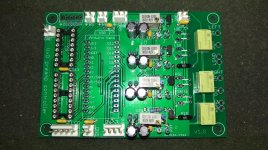
What sort of pins did you use for the input and output terminals on the rhs of the pcb Vincent?
I used breakable male pins from a 0.1" pin header strip, like the ones that you solder on the Arduino Nano.
- Home
- Source & Line
- Analog Line Level
- Arduino based LDR volume and source selection controller