Hello Sorin,
i just sent a mail to farnell since i ordered them 3 weeks ago and got told these will be availlable again next year. i got an answer and they told me they had a technical problem.
thanks for pointing it out!
i have all the other components apart from some resistors and the display,
cheers
J
i just sent a mail to farnell since i ordered them 3 weeks ago and got told these will be availlable again next year. i got an answer and they told me they had a technical problem.
thanks for pointing it out!
i have all the other components apart from some resistors and the display,
cheers
J
I just ordered that from farnell. They seem to have stock and you can order there the LDRs as well. Here are the links I used:
NSL-32SR2. - ADVANCED PHOTONIX - Optocoupler, Photocell / LDR Output, Axial, 4 Pins, 25 mA, 2 kV | Farnell element14
FDV301N - ON SEMICONDUCTOR - MOSFET Transistor, N Channel, 220 mA, 25 V, 3.1 ohm, 4.5 V, 850 mV | Farnell element14
These are in romanian, since I ordered from Romania, so you'll have to search for them in the german site. Or change the language?
Rest of the components I ordered from mouser. They offer free shipping I think over $60 or so. If you need a mouser order list, I have that for the V1 board - IO, PSU, CTRL (bought the boards a long time ago, never had time to get to assemble them).
Cheers,
Sorin
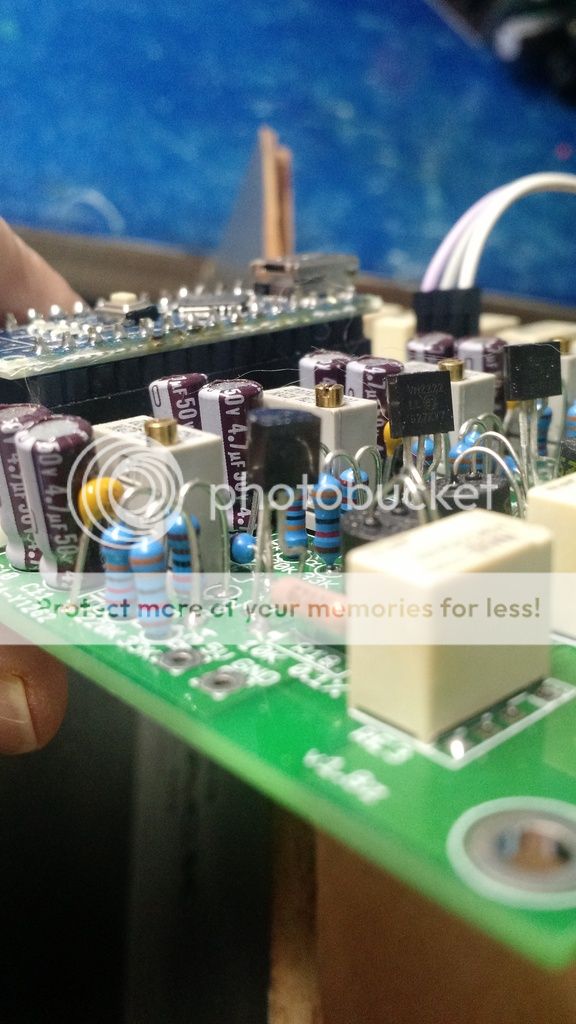
Or you can use the replacement for the 5LN01, VN2222LL-G and just bent the leads a bit. See pic:
RS in the UK have increased the cost by ~44% for the same 100off rate. And much higher if only 50off (+157%) are bought.
Thanks all the help,
Farnell sent the 5pcs. after they sorted out their "systemfault".
already soldered 🙂
i might post some pics when i finished soldering
Farnell sent the 5pcs. after they sorted out their "systemfault".
already soldered 🙂
i might post some pics when i finished soldering
Anyone tried a design with ESP8266 ?
You mean like, to design same thing from scratch on a totally different platform? I don't think so😉
ESP8266 should be compatible with Arduino, with the added benefit of having wifi available as well. So potentially you could remotely operate it with your cell phone. I heard the wifi part is not that reliable though, but I have not tested myself.
Also, not sure how much memory it has available.
Also, not sure how much memory it has available.
It's not totally different, I could easily adapt your code. NodeMCU or weMOS are interesting for this use. I'd do myself, but I lack skills with PCB design.You mean like, to design same thing from scratch on a totally different platform? I don't think so😉
I use it for a pair of IoT projects. Not bad at all.ESP8266 should be compatible with Arduino, with the added benefit of having wifi available as well. So potentially you could remotely operate it with your cell phone. I heard the wifi part is not that reliable though, but I have not tested myself.
Also, not sure how much memory it has available.
I finally started building this, more than 1 year after I got my PCBs. In the meantime I figured I need more IOs than the 3 in x 1 out board I have on hand.
Anybody has any of these PCBs available:
- IO board - 4 in x 2 out
- IO board - 3 in
- all in one with 4 in x 2 out
- anything else that may apply 🙂
Thanks,
Sorin
Anybody has any of these PCBs available:
- IO board - 4 in x 2 out
- IO board - 3 in
- all in one with 4 in x 2 out
- anything else that may apply 🙂
Thanks,
Sorin
I found this line:
att = getAttFromStep(i + 2);
so if I need Vr = 1/2 Vl
then I can use smt like: att_r = att - 6;
and apply to below block?
I appreciate if any one can help me on this?
att = getAttFromStep(i + 2);
so if I need Vr = 1/2 Vl
then I can use smt like: att_r = att - 6;
and apply to below block?
I appreciate if any one can help me on this?
Hey thank you for sharing you DIY project! I will solder off the ldr's from my lightspeed/lighter note attenuator and make this, hopefully the ldr's will survive another heat cycle from the soldering iron 🙂
Again, thank you 🙂
Again, thank you 🙂
Anybody tried to integrate a headphone amp in the same chassis as the LDR attenuator?
I am thinking of putting in a headphone amp connected to the secondary output (4 in / 2 out AIO version here). I'm planning on controlling it with the arduino and a separate relay, so it gets turned on only when I select the output to headphones.
I have seen that initially there was planned a delay relay for soft starting a tube preamp, and I am curious if anybody has more info on how to use this functionality to turn on the headphone amp instead.
So my questions would be:
1. Where exactly on the board to connect an additional relay for this
2. What kind of relay should I use? Latching / non latching? Assuming 5v / 220V?
3. Where exactly should I alter the code to support the functionality?
Hopefully some of you would have some answers. If not, I can try hacking it myself and post here the results, if I get any 🙂
Thanks,
Sorin
Anybody tried to integrate a headphone amp in the same chassis as the LDR attenuator?
I am thinking of putting in a headphone amp connected to the secondary output (4 in / 2 out AIO version here). I'm planning on controlling it with the arduino and a separate relay, so it gets turned on only when I select the output to headphones.
I have seen that initially there was planned a delay relay for soft starting a tube preamp, and I am curious if anybody has more info on how to use this functionality to turn on the headphone amp instead.
So my questions would be:
1. Where exactly on the board to connect an additional relay for this
2. What kind of relay should I use? Latching / non latching? Assuming 5v / 220V?
3. Where exactly should I alter the code to support the functionality?
Hopefully some of you would have some answers. If not, I can try hacking it myself and post here the results, if I get any 🙂
Thanks,
Sorin
I have the headphone amp in the same chassis, but is turned on along with the preamp. Not sure why you want to bother and fiddle with power pops while switching the output channels, unless you have a tube headamp.
It's not tube. I thought I would not have the headamp turned on when not needed. Most of the times I'll listen through speakers, so headamp not needed most of the time.Not sure why you want to bother and fiddle with power pops while switching the output channels, unless you have a tube headamp.
I don't think it's worth the effort. Consumption of the solid state headamp is negligible.It's not tube. I thought I would not have the headamp turned on when not needed. Most of the times I'll listen through speakers, so headamp not needed most of the time.
It's not tube. I thought I would not have the headamp turned on when not needed. Most of the times I'll listen through speakers, so headamp not needed most of the time.
I don't know the circuit details, but it's possible that having the headphone amp in the circuit, driven, and powered off could damage the headphone amp. Various semiconductors like op amps might have their input terminal voltages driven by the main output signal beyond the voltage at the power supply terminals (which are at 0V when powered down), and that can permanently damage them. The same goes for transistors - some junctions could be reverse biased, which may damage the device. It's also possible that the amp will place a nonlinear load on the main output when it's not powered up, injecting distortion into the main signal. This would be similar to loading the output with a diode - never a good idea.
I'd skip that idea entirely unless you can also make sure that the signal to the headphone stage is also disconnected. Overall, it seems excessively complicated for no benefit. Having the extra load on your power supply regulators will make them work better anyway, so just leave the headphone amp powered on.
- Home
- Source & Line
- Analog Line Level
- Arduino based LDR volume and source selection controller