Just to clear one thing up, I didn't run the amp without the insulation on the MOSFETs. I literally switched it on to see if the fuse would blow. It didn't, the light went to green and i then switched it off. I doubt that any damage would have occurred during that test. Maybe something was damaged before, or maybe something was not fitted 100% during my repair.
I just need to try and work out what's wrong now.
I just need to try and work out what's wrong now.
To be honest I think if it came on and light went green you're OK. There mustve been enough insulation that you "got away with it". If there hadn't been, you'd have had a direct +V to -V short via the MOSFET cases, and probably a big bang.
I would start by checking the voltage across R1/R101. You want to measure ACROSS this resistor, in millivolts mode on your meter.
Cutting out when the volume is turned up sounds like the VI protection is kicking in when it shouldnt be. It could also be that one side of the circuit is not functioning at all, giving a distorted waveform which is triggering protection. You could only really easily see that with a 'scope.
To sum it up, so far you have:
* Replaced the power supply capacitors
* Replaced other electrolytics ?
* Replaced the output MOSFETs
* Replaced the supply rectifier diodes D201-D204
Anything else?
Last edited:
Yes, that's it.
The 4 NMOS,
the diodes D201-204,
the capacitors at C201 and 202.
I have bought capacitors to replace the C3 and C103 but not done yet. And I bought a LM393 dual comparator which I have not used.
I will check R1/101
Thanks....
The 4 NMOS,
the diodes D201-204,
the capacitors at C201 and 202.
I have bought capacitors to replace the C3 and C103 but not done yet. And I bought a LM393 dual comparator which I have not used.
I will check R1/101
Thanks....
Always check the DC conditions, namely DC offset and bias current.
If its distorted on headphones then that suggests something other than a simple biasing issue, it could even be oscillating/unstable and that is really 'scope territory to confirm and diagnose.
The failed diode was a definite fault... but you did a lot of other work on the amp I think. You need to backtrack and look at everything you have done.
Not that much really. First step was replacing the 4 mosfets. Tried again and it was still blowing the main fuse. Changed the diodes and then it switched on OK and the power light went green and I assumed OK. Then replaced the power supply capacitors and it tested OK again.
Then didn't actually run it until yesterday when the distortion and cutting out became apparent.
Then didn't actually run it until yesterday when the distortion and cutting out became apparent.
Check the bias. I said above that as it was distorted on headphones then it could be more than bias but check it anyway. If it was running zero bias then you could get that effect.
Not totally sure on how to do that, but is this along the right lines:
How to Measure DC Offset: 5 Steps (with Pictures) - wikiHow
And yes, one channel of headphone sounds distorted but it doesn't cut out on headphones.
I will probably not be doing anything else until early evening.
How to Measure DC Offset: 5 Steps (with Pictures) - wikiHow
And yes, one channel of headphone sounds distorted but it doesn't cut out on headphones.
I will probably not be doing anything else until early evening.
Last edited:
DC offset is simply the DC voltage appearing at the main amplifier output under no signal conditions. If the speaker relay is connecting the speakers then you can simply measure this voltage across the speaker sockets without even taking the top off.
If the relay isn't connecting (due to a fault) then you simply measure the voltage before the relay.
Voltage for an amplifier with a DC servo (such as this) should normally be under 5 millivolts or so but as this amp seems to use an NE5534 opamp for the servo (rather than the more normal FET type) then the offset could be higher.
No amplifier should have more than -/+100mv, most come in under -/+20mv and most well designed servo types should come in under -/+5 mv
Also check the bias current as per the service manual.
I will get on to that later and report back. Might not be until 6pm, unless I get a moment between now and then.
Thanks again.
Thanks again.
short the input with a dummy zero ohms RCA plug. Short both. Then test output offset (mVdc) and output Noise+Hum (mVac)
leave the speaker output open.
leave the speaker output open.
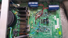
OUCH. No. Do not do that with the power supply capacitors. It will not be causing your fault, but it WILL impair the amplifier's performance, as those long wires are effectively inductive resistance. Put the old capacitors back in if the new ones dont fit in place.
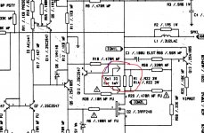
Measuring bias can be done as i described, by measuring millivolts across resistor R1/R101. Bias current is then mA = mV / 0.22
edit: Just spotted RA1/RA101 on the schematic, so thats actually 0.11 ohms resistance. So ias current is then mA = mV / 0.11
Measuring bias can be done as i described, by measuring millivolts across resistor R1/R101. Bias current is then mA = mV / 0.22
edit: Just spotted RA1/RA101 on the schematic, so thats actually 0.11 ohms resistance. So ias current is then mA = mV / 0.11
As you can maybe see from my picture there are some small components around the base of the old locations that prevent mounting of these larger cans. I was lead to believe having flying leads was OK?😕
I just powered up and connected my dac/headphone amp at minimum volume. I set multimeter to 200mV and got readings around -7.0 from all four speaker outputs. I switched between each pair.
I can plug one speaker into either of the two left channels on its own and it's fine.
Right channel low output and distorted then trips as volume turned up on pre.
Just using my second set of speakers, Cyrus 780's, LF input only.
Headphone same but without tripping.
Right channel low output and distorted then trips as volume turned up on pre.
Just using my second set of speakers, Cyrus 780's, LF input only.
Headphone same but without tripping.
What you have just posted suggests something else is amiss. Low bias would not cause an amp to trip, the only noticeable effect would be distortion (and maybe not that obvious in some amps) at lower levels.
If its tripping out then you have some other issue at work. Having said that, check the bias because it is all 'evidence' as to any potential problems and where they may lie.
If its tripping out then you have some other issue at work. Having said that, check the bias because it is all 'evidence' as to any potential problems and where they may lie.
- Status
- Not open for further replies.
- Home
- Amplifiers
- Solid State
- Arcam Delta 290P keeps blowing fuse