-15V returns to analogue ground. The chip uses the 10V difference between -15V and -5V as a reference so -5V should be decoupled to analogue ground too ?
Another question on the Arcam, why does the CCS biasing Iout appear to give 1.6mA instead of 2mA ?
Another question on the Arcam, why does the CCS biasing Iout appear to give 1.6mA instead of 2mA ?
on the Arcam -5v supply so add one, tight to the dac, to its analogue 0v ground. Try 0.1uF film cap or 10uF oscon
I'm interpreting this as a cap between pin 26 and pin 5 ( with the neg of cap to pin 5 - VDD1 to GND A - right on the chip)
Is that correct ?
John, on CCS biasing - I don't know - sorry
Andrew, yes thats the way to do it, but Simon's later post suggests it is not needed. So fuggedaboutit.
Simon - thanks for the clarification.
I should have added - most older style 3-pin regs do not need a cap on the output for stability (eg the 317), it's only put there on the datasheet as a 'serving suggestion' because it helps transient performance at the load. Arcam may have had a reason to omit the cap at the reg, they may not.
However - newer 'LDO' 3pin regs often do require a cap directly on the reg's output as do most superregs, because the cap also supplies whats called 'compensation' - it is required to ensure basic stability/functionality. So you can't just rearrange as you like with impunity either!
Last edited:
Martin...a new word - fuggedaboutit ?
I also toiled over Simon's ' elco ' 😀
John also observed only the 100 uf + 47nf and I've and a look and it seems there are 2 x 100uf's - one by the reg and one by the chip plus the 47.
Andrew
fyi - I chased down the hum on my valve buffer - 2 weeks nearly. Knackered valve - so glad it's just this and now I can case it all up in readiness for the new bottles. FINALLY !😉
Andrew,
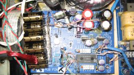
C221 (100uF) + C222 (47nF) are on the -5V by the DAC (but decoupled to DGND not AGND). AGND is decoupled to DGND via C227 (47nF). If you're talking about C226 by the -5V reg (Z204) that's on the adj pin.
Jon
C221 (100uF) + C222 (47nF) are on the -5V by the DAC (but decoupled to DGND not AGND). AGND is decoupled to DGND via C227 (47nF). If you're talking about C226 by the -5V reg (Z204) that's on the adj pin.
Jon
Guys - I just took a GIANT step tonight.
OK you were all ahead of me in the output stage stakes anyway but I've just ( finally ) sorted my valve output stage properly.
The hum and odd noises are all gone and I have lifted the equivalent of a plank of wood away from the front of the speakers - 😀
It's astonishing and has improved the whole delivery - everywhere and in every department.
I raved about silencing the 7220, all the clock stuff and the large DAC traffo but this is about the equivalent of all three !!
The 6N6P valves are not soft or bloated, warm or loose sounding - they're rock solid and there's loads more bass information in terms of pitch, and I've got texture and real edges to the sound of bass instruments - where the hell was that hidden all this time ?
The question is then : How much of the original output stage can I remove and is there a sonic gain to be had in stripping it all away ?
I don't want to ' goose it ' now it's running as it should.
I'll put some pics up tomorrow - it ain't glamorous yet but hell, I don't care 😉
Andrew
Guys - I just took a GIANT step tonight.
The question is then : How much of the original output stage can I remove and is there a sonic gain to be had in stripping it all away ?
Andrew
Congratulations Andrew! It is quite magical isn't it.
The answer to how much can you remove? All of it! Every last opp amp.
I pick the signal right off the output pins. See picture below. I actually pick it up at R3 and R103 for convenience. I ripped the little opamp devils off the board to stop them stinking the place up!
It would be better even better right at pins 5 and 25.
As EC Designs says, get rid of them all.
Andrew, using 6np6 you may have to leave the first op amp. At some point, it would be interesting to test picking up the signal before the op amps and see if you have enough gain to drive the 6np6. Worst case, join me in using 6n2p. They are equally great, just different, but with 10x more gain. Once you prove that you can steal signal without opamps, time for an opampectomy. With a pair of pliars you can pull them out like a bad tooth. Even after you stop using them, things get better just getting them off the power supply as they pollute that as well.
Attachments
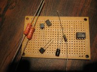
Series Reg
Next up, DIY Reg
Parts arrived just in time for the weekend. Time to try Peter & Bobkin's Series reg. Hopefully a cost effective answer. I stayed away from their exotic resistors that can run $15 ea. I stayed with Takman & Alan Bradley. I am playing around with surface mount organic polymer cap at 8.2u. EC Design recommends soldering right on the pins for better effect on 1541. Maybee good here too. We'll see. I picked up some small BG just in case for backup. Both are under 1$.
Andrew - looking forward to pictures and more listening impressions. 🙂
Walter
Attachments
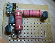
Reg Works
After a couple of hours of fussing about, my first regulator springs to life.
The description suggested a 5k resitor to produce 5V. In fact it produced more like 7.3. So I tried resistor after resitor and found that 45R caused it to produce 4.9V. Close enough. I figure I can put a variable pot on it in the future and find the exact value to produce 5V under load.
Its late so I'll put it in another day. As I experimented I did see you can dial in 3.3V so I am going to be able to use this circuit for the supplies on the USB-IS2 source. If it sounds good I'll be building a few of these.
Attachments
Not for this application
Turns out this is not going to work in this application. The reg works perfectly without the load, but it just cannot deliver enough power to satisfy the 1541a demands. After many attempts I had to back it out and reinstall the LM317 reg.
I must say, I thought I would be building a new 1541a board. In my attempts to power this thing it would slowly drift up to 5V and then break down and flash 20v +. I never expected the 1541a to survive this weekend of experiments. I put the 317 reg back and powered it up. Voltages were a bit scattered all over the place. The 317 fed about 5.3v. My Burson was also a bit off at -5.13. I thougtht what the heck, let's plug it in and see what havoc I have done to my rig.
Unbelieveable, it just fired up and plays great music. The 1541a is one tough Mutha.. In the process I had shortened the leads to move the -5v Burson shunt reg closer to its consumer. I believe this has made an improvement to the sound stage. Maybe the 1541a likes a little higher voltage. Maybe I'm just greatful that I have my rig playing again. I don't know... the sound it amazing.
I think this reg will work fine in a less current demanding spot. I'll try it on my clock... but not today. Time to just enjoy the sound!
cheers
Walter
Attachments
How lucky have we all been ?😱
It we don't push the envelope we'll never know where the limits are.
Very interesting regs you built there and look simple enough.
Must admit I don't know how much current the TDA pulls or needs. Have you been able to ascertain how many ma's your reg is capable of ?
It must be good for something if Peter Daniels is using ( and designed ) this too ?
Is it related to his 1543 dacs by any chance ?
Going to strip away some of the garbage from the output stage today and order some i/v resistors to have a go directly off the chip - 68 ohms OK ?
PS was coming on quite well until I wired in another traffo and the damn thing heated up so much I had to switch it all off in a hell of a hurry.
You would have had a laughed if you'd seen my panic.........😱
Changed the bridge - same problem - changed the big cap and all was well.
Do old caps just short themselves or something ?
The valve stage post earlier was no placebo - it's still the same and I'm SO glad I persevered with it - it's only going to get better too.
If the 6N6P's don't have enough gain are the 6N2P's noval's and is the wiring of them the same - pin 6 for ht, 4 and 5 for heaters, and pin 9 for ground etc ?
It would be great if it was a straight swap.
I finally think I may be coming to the end with this player once I get the PS sorted and the regs done - can't believe I'm saying it - only 2 more jobs to do - surely not ?
Maybe i2S but hey that's only 3 jobs then.....!!
Andrew
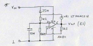
That 'voltage reg' may be designed to drive a reference pin on the TDA1543 or similar but it's a really poor regulator. For a start, it isn't going to deliver more than 25dB or so of ripple rejection . And any noise benefit from using the LM811 is lost due to the high source impedances it 'sees'. Finally, it's output current is very, very limited. Definitely not a superreg!
Edit for afterthought - I think there's somethign wrong with the diagram as posted. rearranged as a more conventional series reg it'll do a bit better than I suggest above, but it's not optimal.
Is it related to his 1543 dacs by any chance ?
Going to strip away some of the garbage from the output stage today and order some i/v resistors to have a go directly off the chip - 68 ohms OK ? -
are the 6N2P's noval's and is the wiring of them the same - pin 6 for ht, 4 and 5 for heaters, and pin 9 for ground etc ?
It would be great if it was a straight swap.
Andrew
Yes.. Peter has a thread "pushing the limits of 1543 DAC. He, Bobkin and Uncle Leon have pushed his dac to another level ... shunt regs described, but Peter commented they got nearly as good results using this series reg. I will try mine on the clock.
Glad to hear the valve stage worked out so well.
68 Should be fine. I am likely high at 90. One guy claims he's measured distortion at higher values. Others prefer the sharper edge at 90-100.
6n2p is a drop in replacement, but the filament current is much lower so you'll likely need to increase the resistance in the CRC filter up to 5 - 10 ohms to get 6.3 V.
Edit for afterthought - I think there's somethign wrong with the diagram as posted. rearranged as a more conventional series reg it'll do a bit better than I suggest above, but it's not optimal.
Thanks Martin. I'll try it on a low load pin somewhere. I'll check with the designer to see if they are sure they penned the design correctly. Otherwise sounds like its back to the drawing board. I was attracted by the simplicity and low parts count.
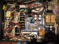
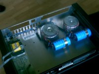
Couple of update pics - power supply as of Sunday gone and the valve buffer.
One more traff to fit to the ps plus the fittings / fixings and then a test as early as Friday hopefully. Also the dac board will be completely stripped of it's original output stage too.
I've decided it's too complicated and probably stupid to attempt the idea of powering the whole player from this external box. So I'll leave in the main player the original larger traff and have the clock ps only.
The DAC traffo will be in the new box as per photo.
Simon - what happened when you switched your external on for the first time - was the extra headroom obvious ?
I mean - what can I expect in terms of sonic gains ?
I hope it's another step up anyway.
Walter - forgot to ask - my 68 ohm passive i/v resistors - what wattage should I use ?
2 watt - 5 even ?
Thanks
Andrew
Attachments

Andrew
Nice job! Both look great. I particularly like your tube buffer.
re wattage, others should weigh in with advice. I followed lampizator guide and used 1/4W, and am happy with it. I vaguely recall somone advocating non inductive higher watt resistors. I have not experimented. I simply bought Takman resistors and put it together. Mine is in confined space and not really good for parts comparison. By the time I build it up and add small poly bypass caps on the tube socket etc, it is not easy to get a soldering iron in to change parts. So I can olny offer that 1/4w seems to work well.
Still happy with the sound?
Walter
- Status
- Not open for further replies.
- Home
- Source & Line
- Digital Source
- Arcam Alpha mods