Maybe. If there is a problem it could turn out to be a more insidious one, one not quite so obvious yet still some audible effect.Maybe I will notice this when they use it , because of the fast opamp-buffer.
Maybe I could put it this way: Some people take the position that if we don't notice a problem then it doesn't matter. However, in some of those cases once somebody points out a problem then we can't stop noticing it. Depends 🙂
EDIT: A suggestion for you regarding LME49600 -- IIRC it has a bandwidth setting pin. Seems like most people tend to set it for maximum bandwidth, presumably thinking 'more is better.' Might be worth experimenting to see if you think there is any difference in SQ with it set either to maximum or minimum BW?
Last edited:
Phase shift through the x1 output buffer directly reduces stability ("phase margin") of the composite amplifier. That's why the LT1010 datasheet includes guaranteed specifications on phase shift -- to let you know just how much worse your composite amp will be, than the opamp alone.
The lower the bandwidth of the x1 output buffer, the greater its phase shift, which means lower phase margin and greater danger of instability for the composite amplifier as a whole. TANSTAAFL.
The lower the bandwidth of the x1 output buffer, the greater its phase shift, which means lower phase margin and greater danger of instability for the composite amplifier as a whole. TANSTAAFL.
About the BW selection . For me that likes low quiescent currents , obviously I'd choose low bandwidth with 7,3 mA BUT datasheet of the LME, top of pg 13 says : When the LME49600 is driving high value capacitive loads , the BW pin should be connected to the VEE pin for wide bandwidth and stable operation. The wide bandwidth mode is also suggested for high frequency , fast-settling opamps .A suggestion for you regarding LME49600 -- IIRC it has a bandwidth setting pin. Seems like most people tend to set it for maximum bandwidth, presumably thinking 'more is better.' Might be worth experimenting to see if you think there is any difference in SQ with it set either to maximum or minimum BW?
My HP wires are 5 m long and bigger than the thin original ones so more pF , and the OPA828 is a high frequency , fast-settling opamp , so wide bandwidth it is. To keep the connections between the BW pin and VEE short , it will be on the other side of the PCB , where it is very hard to change the bandwidth with a resistor or even to leave it open for the low setting.
How about using one opamp wrapped around the buffer at a unity gain then the 2nd opamp wrapped around them both to take care of the gain? Ive seen this done by a japanese designer and the benefits seem numerous
IMHO, fast and beefy CFB opamps serve best for power buffer when significant total circuit gain is required.
You can run a THS3491 at 10x with no effective phase penalty for most any "audio" OpAmp with typical GBW (like 50MHz tops) and by this the master OpAmp operates at unity gain even at 10x nominal circuit gain.
You can run a THS3491 at 10x with no effective phase penalty for most any "audio" OpAmp with typical GBW (like 50MHz tops) and by this the master OpAmp operates at unity gain even at 10x nominal circuit gain.
Higher input impedance for the buffer stage+ lowered distortion. Basically u get a better performing buffer but its also more feedback. I might prototype this with 1656 and buf634a and find out how it soundsSo what are they ?
Again I will express a differing opinion to the effect that more feedback does not necessarily lead to more accuracy of reproduction, if one takes noise modulation into account. OTOH if the only criterion is minimal FFT HD spurs more feedback can give more so-called linearity.
@Markw4,
You've been playing this record for years, and as far as expressing an opinion this is fine of course, but where's the data?
I've developed means to look at least 30dB into the noise floor in the time domain with arbitrary signals and found all kinds of stuff in subtractive analysis at those microscopic levels, like DAC and/or ADC gain modulation with signal (Vref modulation of AK449x), and of course normal distortion products and such, but never any hint of noise floor modulation... and I don't think it can exist anyway. How could an precision composite amplifier with tons of feedback for correction even at 20kHz, say, the Groner/Polak circuit, have any noise floor modulation? This is not DACs where noise floor modulation may actually exist.
Seems to me something similar can happen if there is RF present. Its known that modern opamps are increasingly specified for tolerance to incoming RFI/EMI that might otherwise produce demodulation of RF in input stage transistors and or ESD protection diodes, then possibly remodulation with signal. Forward biased semiconductor junctions can serve both demodulating and modulating functions. Obviously RFI/EMI is present in dacs, but its also present in many devices that use SMPS. Also, environmental noise may find its way into amplifiers through I/O connections. Nothing new to such things.
For one example, I have a Neurochrome HP-1 HPA. IIRC it is an opamp and LME49600 design. It has a three position gain switch in addition to a volume level knob. The gain switch changes the gain and the sound, with lowest gain setting presumably selecting the most negative feedback. The lowest gain setting also produces the most anomalous sound. One easily heard change in the sound depending on gain setting is what some people refer to as 'splash.' The term refers to things like the sound of cymbals tending to sound more like bursts of noise rather than like real cymbals. Doesn't necessarily seem to be a product of HD, so what's left that could account for it?
Also, depending on the exact process by which noise is intermodulated with signal, the symptom might be slight widening at the skirts of a spectral line on an FFT rather than appearing as a shift noise floor level. That's the kind of symptom seen in radar returns as a function of clock close-in phase-noise.
Last edited:
My project reached measurement and evaluation phase. This composite amplifier is different from the all available so far as it has super regulators on board, separate for each channel. That way, simple dual rail PS from +- 18V to +- 60V can be used. Intended use is as input buffer in power amplifiers, for driving line transformer VAS instead of usual puny JFET buffer.

As regulators are used OPA551 operational amplifiers. They provide wide supply power bandwidth and excellent transient response up to 270 mA, where current limiting kicks in.

Distortion is very low and on verge of my equipment (Focusrite Solo gen. 3). Equipment introduced distortion is 0.0003 % (loopback measurement). So, amplifier distortion at 1 V rms output to 32 Ω load is 0.00024. It is nice that only H2 distortion was added.


Stability with capacitive loads is very good.


With no C5, F3 frequency is exactly 2.5 MHz. Square wave response at 100 kHz is perfect. Desired frequency response can be adjusted with R1-C5 RC filter.

If someone wants to build this, I can provide gerbers for modified PCB with fastening holes, so it can be mounted in proximity of input potentiometer. PCB has 4 layers because it was necessary to provide clean and continuous copper areas as heatsinks. One layer was used as Zero Signal Plane and input tracks are in sandwich between two ground planes. Attached measurements were done on the open bench, 20 cm apart from bulky unshielded transformers of old linear PS. On output noise measurement, 50 Hz EMI is et very low level.

As regulators are used OPA551 operational amplifiers. They provide wide supply power bandwidth and excellent transient response up to 270 mA, where current limiting kicks in.
Distortion is very low and on verge of my equipment (Focusrite Solo gen. 3). Equipment introduced distortion is 0.0003 % (loopback measurement). So, amplifier distortion at 1 V rms output to 32 Ω load is 0.00024. It is nice that only H2 distortion was added.
Stability with capacitive loads is very good.
With no C5, F3 frequency is exactly 2.5 MHz. Square wave response at 100 kHz is perfect. Desired frequency response can be adjusted with R1-C5 RC filter.
If someone wants to build this, I can provide gerbers for modified PCB with fastening holes, so it can be mounted in proximity of input potentiometer. PCB has 4 layers because it was necessary to provide clean and continuous copper areas as heatsinks. One layer was used as Zero Signal Plane and input tracks are in sandwich between two ground planes. Attached measurements were done on the open bench, 20 cm apart from bulky unshielded transformers of old linear PS. On output noise measurement, 50 Hz EMI is et very low level.

It’s stable because it provides DC output. It couldn’t drive large capacity with AC signal.
Transient loads up to internal current limiting are not an issue.
edit: Just remembered that OPA551 regulators were tested with 1000 uF organic polymer capacitors at output as well. Everything was perfect with dynamic loading.
Transient loads up to internal current limiting are not an issue.
edit: Just remembered that OPA551 regulators were tested with 1000 uF organic polymer capacitors at output as well. Everything was perfect with dynamic loading.
Last edited:
Loop stability could be an issue though. Regular opamps cannot realistically cope with almost pure capacitive loads (there are some exceptions, but they are rare).
It would be a good idea to sim the circuit if a good OPA model is available. Otherwise, a real-world test is not difficult to setup: a function generator, a 100ohm limiting resistor and a 100µF DC-blocking capacitor.
You just have to sweep the frequency from a few Hz to 2MHz or so to detect any peak in the supply impedance caused by a resonance. Damping the capacitor(s) with a small series resistor would then be the cure
Regulators were tested with my “usual method”. Varying frequency square wave load with 1 us rise time, up to triggering internal current limiting and observing transient response. There is direct relation between transient response and phase margin. Paper is attached. According to this method, regulators were very stable.
Actual complete circuit measurements provides no trace of any instability. Frequency response was measured with 2.83 V rms in to 32 Ω load, observing output sine wave with oscilloscope. No trace of any harmonic or oscillation.
Actual complete circuit measurements provides no trace of any instability. Frequency response was measured with 2.83 V rms in to 32 Ω load, observing output sine wave with oscilloscope. No trace of any harmonic or oscillation.
Attachments
And as an HP amp.Intended use is as input buffer in power amplifiers, for driving line transformer VAS instead of usual puny JFET buffer.
Some impressive numbers and graphs , and the stability with high capacitive loads is very good .
Gain 2,4x and I see you used the 33pF compensation (C10) and in high bandwith mode with no osillation.
PCB with 4 layers while some do it with only 1.
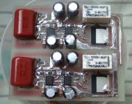
Just finished mine , pretty amateuristic on 2 layers milled PCB . haven't connected it yet , waiting for the heatsink for the 2 LME's .
Attachments
Yes, in essence this is a HP amp.
It is how it works that counts the most, not how it looks. 🙂
It is very likely that you’ll get very good results as well.
Nothing wrong with only 1 layer PCB. I had to use 4 layers because of using both front and back copper areas as heatsinks.
It is how it works that counts the most, not how it looks. 🙂
It is very likely that you’ll get very good results as well.
Nothing wrong with only 1 layer PCB. I had to use 4 layers because of using both front and back copper areas as heatsinks.
It is a valid method, and if it does not show anomalies, the opamps see enough damping to be stable, in the esr of the capacitors or elsewhere.Regulators were tested with my “usual method”. Varying frequency square wave load with 1 us rise time, up to triggering internal current limiting and observing transient response. There is direct relation between transient response and phase margin. Paper is attached. According to this method, regulators were very stable.
Somewhat unexpected though.
- Home
- Amplifiers
- Headphone Systems
- Anyone make OPA828 - LME49600 combination